Installation Tips - Walthers Lightweight Passenger Cars
I like the looks of Walther's passenger cars a lot. The detail level is not extraordinary, but still very good.
These cars need type H couplers and Prototype Couplers has a Tailor Made coupler just for the Walthers cars. The Prototype Couplers HT1R87K kit not only includes couplers specifically for these cars, but also includes parts for an improved truck mounting setup that provides an improved truck pivot and height adjustment. This conversion page serves as the instructions for these kits as well.
|
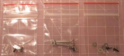
The kit includes three baggies plus a couple of loose pieces of phospher bronze wire. The first baggie on the left includes parts needed to mount the trucks to allow precise height adjustment needed for the tightlock couplers. The middle baggie contains the castings needed for the couplers themselves plus locking balls. The right baggie contains parts needed to mount the coupler to allow side to side movement but hold the length constant. |
 |
|
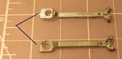
Assembly of the couplers is really no different than assembly of couplers with more conventional shanks. Before you start though, use a file to remove any sharp edges at the back of the top castings that might interfere with smooth operation. |
 |
|
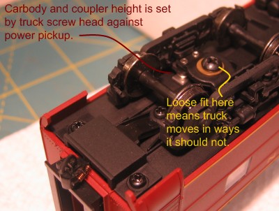
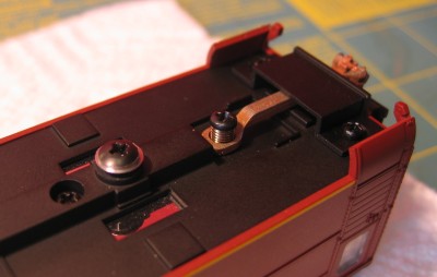
Here's what the underside of the Walthers Pullman-Standard 64-Seat Coach looks like before we start. Before we worry about the couplers, we'll have to address issues with the mounting of the trucks. The factory method used to mount the truck is very interesting. You'll see shiny metal power pickups that the truck screws rest against. This is how the optional lighting kits get their power. The carbody actually rides on the truck screws. As interesting as this is, this arrangement is not without problems. First, there is no easy way to adjust the car height to get proper coupler height. Proper coupler height is very important with Sergent Engineering Tightlock couplers and unfortunately the coupler height varies quite a bit on these cars due to the nature of the power pickup design. Unrelated to the problems with coupler height is the problem of slop in the king pin. If you try to wiggle the truck you'll realize that it's fit to the body is just plain sloppy. The truck should pivot and turn freely, but it shouldn't move from side to side or front and back. This slop will make it difficult to line couplers up in preparation for coupling so we'll have to deal with this problem as well. |
 |
|
To get started, the floor must be removed. First remove the trucks, then the coupler covers, then the coupler arms. Finally, completely loosen the three screws that run down the center sill of the car. Keep the various screws with the parts they attach so you don't mix them up. Some cars don't have the three screws down the center sill. If you car does not, pay careful attention to the orientation of the floor so you don't reverse it when its replaced. |
 |
| With the screws out, the floor can be removed. The side skirts on these cars don't help with this job. The floor will have to be rotated up on one side to clear the skirts on this car. A small screwdriver is used to encouagage the floor to rotate past the skirts. | 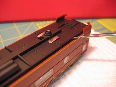 |
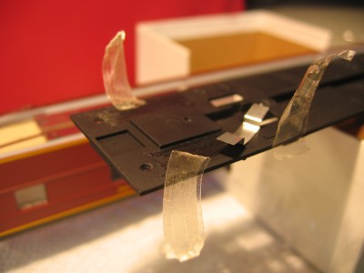
| Be aware that double sided tape is used to hold contact strips to the car floor. Sometimes its used to hold the weight as well. In the picture you can see that the tape has let go of the back strip, but still hanging to the front one. You'll want to slip a screwdriver in there to pry the contact strips away from the tape. | 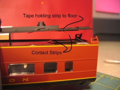 |
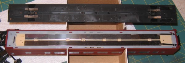
| The picture below shows the floor finally removed. You might be surprised to find out how much tape is used to hold these cars together. There is tape that holds the weights in place and tape that holds the power pickup in place. | |
 |
|
|
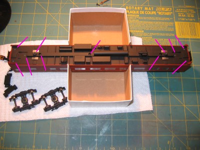
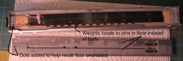
Here's a different car with the floor removed. This one doesn't have the screws that run down the center sill. Notice that I have used a Sharpie to add dots to the floor and body so I'll know which way to orient the floor when I replace it. Unlike the cars with the center sill screws, these cars don't locate the weights on the body but instead rely on pins in the floor. |
|
 |
|
|
Peel, cut, and/or scrape off the tape holding the pickups. Remove that double sided tape on the contract strips as well. Pop out the pickups if they didn't come out with the tape. We won't be using these pickups. Instead we'll fabricate some wipers from phosphor-bronze wire. |
 |
|
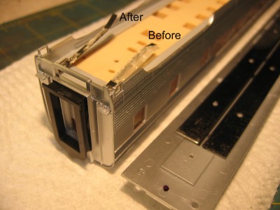
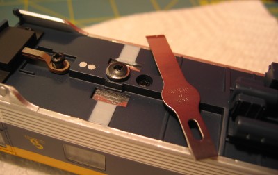
This step is for cars WITH NO center sill screws only. To make reassembly easier, we'll let the contact strips contact the weights from the top instead of the bottom. The contact strips should both be bent as shown in the photo as "After". The weights will also have to be attached to the floor for assembly. I used a dot of super glue in the middle of the weights since it was handy. The weights can't go anywhere once the car is assembled so this doesn't have to be a heavy duty bond. |
 |
|
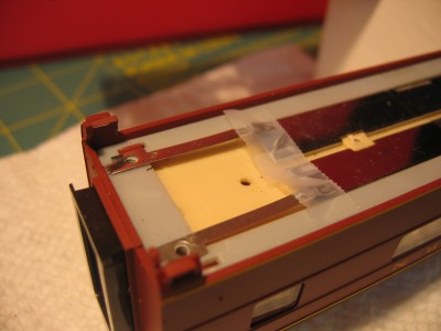
This step is for cars WITH center sill screws only. The contact strips do need to be held in place. We have to make sure the contacts rest completely on the metal weight instead of the gray plastic strips that run down the outboard sides of the car. I guess if tape is good enough for Walthers, it's good enough for us as well. I used a couple of very short pieces of tape to hold the contacts in place. Do NOT use double sided tape. Note that once the floor is replaced, it will hold the contact strips in place so the tape here is mostly just an assembly aid. |
 |
|
Next, we need to replace the floor - leaving out the power pickups. Notice that while the floor can be put in place backwards, the screw holes down the center sill will only line up if the floor is installed the right way. Make sure the hole for the center screw is lined up with the receiving hole in the body of the car. If your car doesn't have the screws down the center sill, then you'll have to refer to your marks (or memory) to ensure the floor isn't reversed. The floor will be rotated into place the same way it was rotated out of the car. Start by putting one side of the floor into place, then use a #17 X-Acto blade to pry back the skirts a bit so the floor can pop into place. Replace and tighten the three centersill screws once the floor is in place. It's important that these screws be in place before any other screws are replaced. |
 |
|
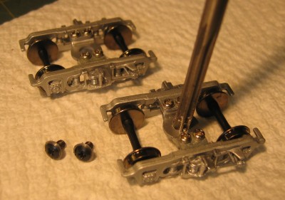
Now its time to prepare the trucks. The king pin screws included with the Sergent Engineering kit have a ledge that is precisely cut to a diameter of 0.212". The hole in the truck bolster needs to be adjusted to be ever so slightly larger than this. The Prototype Couplers RM213 will adjust the hole for a super precise fit with the king pin screws. Just hold the reamer perpendicular to the truck bolster and spin it by hand to enlarge the hole. Since the truck bolster is plastic, this is easy. |
 |
|
The function of the power pickups that were removed will be performed by wipers installed on the trucks. We have to bend up the 0.008" phosphor bronze wire thats is included in the HT1R87A kit to do the same job. (Of course you can skip all this if you never intend to add lighting kits to the cars.) Start by printing out this pdf file that will be used as a template to form the wipers. The first step is to use long nose pliars to bend the loop that will fit under the truck screw shown on the top view. You don't have to be exact - just close. |
 |
| Next, bend the wire back over itself using the side view as a guide to form the actual wiper portion of the wire. Then cut the wire to length. We'll need a total of four of these for each car. |  |
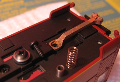
| The wipers are installed as shown in the picture. Just loosen a truck and slip the wiper under it then tighten. | 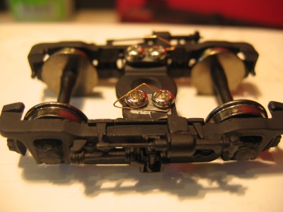 |
|
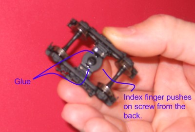
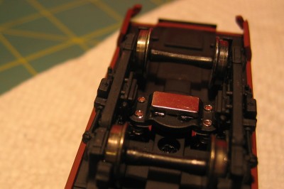
Next we need to attach the magnets to the trucks. The magnets will pretty much hold themselves on when the truck is on the car but they need help when the truck is removed from the car. First put a couple of small dabs of super glue on the truck in locations shown in the picture. Then hold the the truck and a king pin screw in one hand as shown in the picture. (Notice that my index finger is holding the king pin screw in place and also notice that the screw head is behind the truck in the picture.) Use the other hand to position a magnet into place. Once the magnet is there, it will stay because it really likes that steel king pin screw. |
 |
|
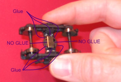
Now that everything will hold together on its own. Add some more glue around the outside of the magnet. Don't let the glue seep through those cracks on either side of the magnet though. The goal here is to pull the king pin screw off once the glue cures. You might be temped to use epoxy or some other type of glue here. I don't recommend it because super glue is unaffected by oil that might be used to lubricate the truck journals. Epoxy will fail if it is exposed to the slightest amount of oil. Just use plenty of super glue and you won't have problems. Now set the truck aside to let the glue cure. You can set the truck right side up since the magnet is in no danger of falling off. |
 |
|
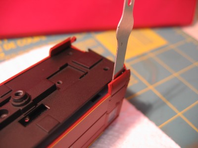
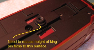
The new king pin arrangement uses a 4-40 screw to provide an adjustment for the car height. One full turn will change the height only 0.025" so very accurate adjustments can be made. In this arrangement, the screw doesn't hold the truck on place. We rely on a super strong magnet for that. The screw head is used to space the truck off the body. The first step here is to make some space for the screw head by reducing the height of the king pin boss to the step surface shown in the picture. |
 |
|
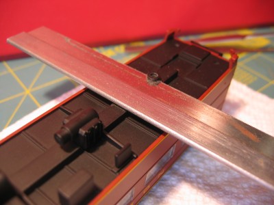
Use a razor saw to cut away the top of the king pin boss. |
 |
|
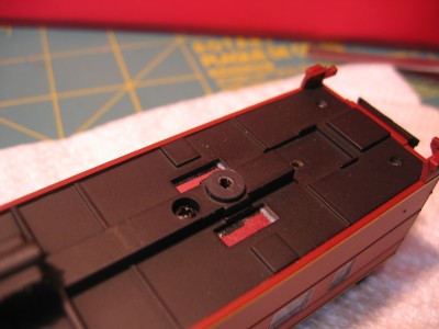
This picture shows the king pin boss after most of it has been cut away. Use a file to clean it up, but don't worry if it's not perfectly square. Rememeber that the truck will ride against the screw head, not this cut away hunk of plastic. |
 |
|
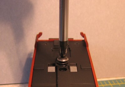
Next, install the king pin screw. The diameter of the hole left by the coarse thread factory installed screw will usually just the right size. The new 4-40 screw will form it's own threads in the plastic as it is installed. Try to guide the screw so it goes in straight as viewed from the end of the car. The right size screwdriver (#1 phillips) will make it easier to keep the screw going in straight. The cut away section of around the outside of the screwhead is where the truck will ride. Don't worry that the thickness of this cut isn't consistant around the head of the screw. What you are seeing is the fact that the screw head is not concentric with the screw threads, but the cut away portion of head is concentric with the screw threads. |
 |
|
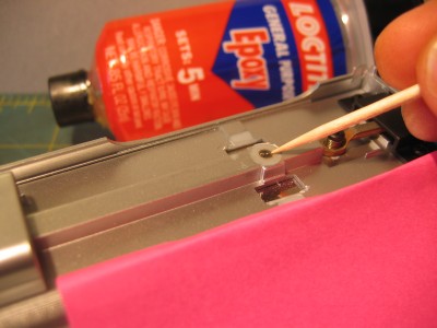
In some instances the hole left by the coarse thread factory screw will be too big for the new king pin screw to thread into. If you run into this problem, spread some 5-minute epoxy into the hole. Notice the pink post-it note draped over the side of the car to protect it from dripping epoxy. Yellow post-it notes work just as well. |
 |
|
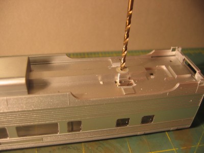
Let the epoxy set for a full 24 hours so it can reach its full hardness (the 5-minute thing is really just an evil marketing ploy). As the epoxy hardens it will create a nice little dish that will work to center a #43 drill used to create a new hole for the screw. |
 |
|
Now set the truck in position on top of the king pin screw and see how it attaches itself. Of course, if you pull the truck will come off. Then you can turn the king pin screw to adjust the car height. Pretty neat, huh? |
 |
|
Remove the trucks because it's finally time to install the couplers. This is the easy part. The screw goes down through the sleeve which goes down through the spring. Use the screws that are included in the HT1R87A kit. Note that one end of the sleeve will be rougher than the other end. Insert the smoother end of the sleeve through the hole in the coupler for the best fit. The spring serves the same purpose as the friction spring in other Sergent Engineering couplers, but it also serves to keep the coupler positioned against the carryiron. You'll see the coupler pop up when you tighten the screw down. |
 |
|
Here it is with the coupler installed and the carry iron back on. |
 |
|
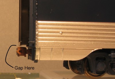
View the car from the side and ensure there is a gap between the bottom of the diaphragm and the top of the coupler. If not, the carry iron will have to be shimmed. |
 |
|
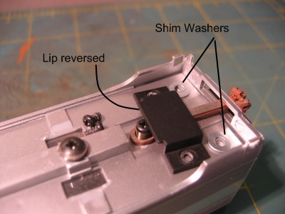
One set of washers is enough to produce the desired gap. Don't use the washers if the there is already a gap without them. Notice that the carry iron for this car has a lip that is meant to fit into the end of the body. Since the shims will keep that from working, the carry iron is installed in reverse. |
 |
|
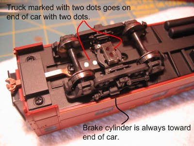
Here it is with the coupler installed and the trucks installed again. Note that the brake cylinders on the sides of the trucks are always closer to the end of the car rather than the middle. The stabilizer rods are always closer to the middle of the car. Since the trucks are pretty easy to remove, it would be pretty easy to swap them. That might affect the coupler height. I used a silver and a black Sharpie to add dots so I can put the trucks on the right end of the car. |
 |
|
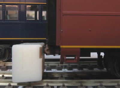
There are will be one and one third turns of the king pin screw from too low to too high on the height gauge. Try to center the knuckle between the two limits. That way irregularities in the track will have the least affect. |
 |
|
The body will interfere with truck movement on some cars. It's usually the brake cylinders or the truck screws themselves that interfere. On this car, I had to scrape away the the body bolster and cut out a little more room for the truck screws. |
 |
|
If the adjustment screw bottoms out and the coupler is still too high, remove the screw and file a little more off of the king pin boss to allow the screw to go farther down. |
|
|
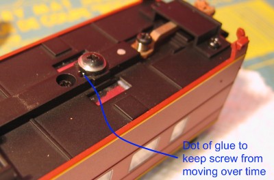
Once the height is set correctly, apply a dot of super glue to the side of the screw to keep it from moving. |
 |
|
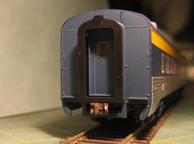
Here's the end view of the car when complete. The tightlock coupler is obvious to those familiar with passenger equipment. Of course, the end is screaming for more detail now - but that exercise will be left to you. |
 |