Assembly Instructions - CST5R87K
This webpage serves as assembly instructions for Prototype Couplers CST5R87K coupler kit. No printed instructions are provided with the kits.
These couplers are tailor made to replace the fixed drawbar on Stewart Hobbies FT A/B sets. Most prototype FT units were delivered as an A/B set with only a connecting drawbar between them, but some were fitted with couplers between the units. This was a challenging undertaking for the prototype because there was no room for draft gear. The trucks were simply too close to the end of the car bodies. The couplers used for this purpose were not standard type E couplers, but a controlled slack variety referred to as a "Santa Fe" coupler on Southern Railway drawings.
Here is a link to a picture of an FT A unit being used without the B unit.
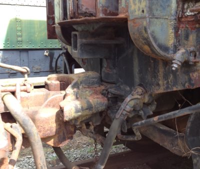
Here is a link to a picture of the front end of a B unit that is typically hidden by the A unit.
Note that these tailor made couplers are not intended for the front of the A unit or the back of the B unit because standard type E couplers are more prototypical for those locations. The "Santa Fe" couplers were only used between the units of the locomotive (or locomotives if you like).
Much of the research for this product was done by Ernest Puddick who supplied the model you see below.
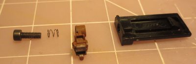
| Shown here are the contents of the kit - enough castings to build two couplers plus locking balls, springs, and screws to attach the couplers. | 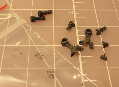 |
|
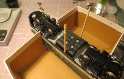
Coupler assembly is no different than any other Prototype Coupler kit. Paint, assemble, break-in; you know the routine. We'll just skip that and go straight to the installation. This sequence shows installation on the A unit, but installation on the B unit will be very similar. The coupler mount was very loose on this unit and I didn't like that, so I decided to remove the shell and see what I could do to tighten it up. Start by removing the coupler on the A end so the shell can slip off. I placed the locomotive in my makeshift cradle. Pay attention so you don't damage the horns on top of the unit. I inserted a couple of toothpicks to hold the locking tabs out of engagement. Once the loco is turned over, the mechanism will slip right out of the shell. |
 |
|
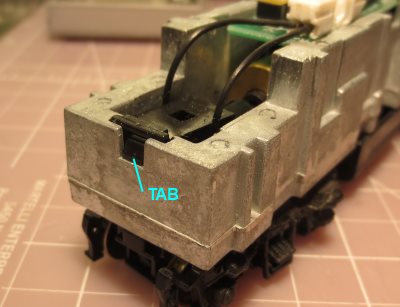
The coupler mount on the Stewart model snaps into the frame. Press the tab to drop the mount out of the frame. |
 |
|
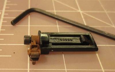
Here's how the coupler is attached to the mount. |
 |
|
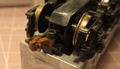
Use a 5/64" hex key to attach the coupler to the mount. Tighten and then back off one full turn so the coupler is free to move. |
 |
|
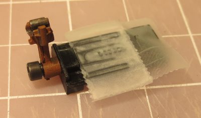
I decided to tighten up the fit of the coupler mount in the frame by just building up the thickness of the mount with tape. This actually worked out pretty well. Three layers of tape seemed to be perfect. |
 |
|
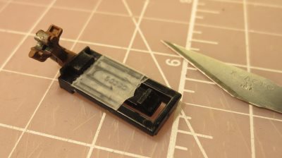
Here's the "thickened" mount after the tape was trimmed. You'll want to test fit and add or remove tape as needed to get a snug fit. |
 |
|
Here's what the assembly looks like when it's snapped back into the frame. |
 |
|
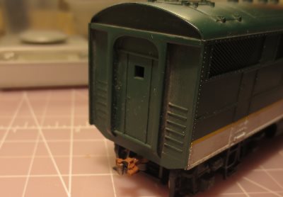
Here's the finished product. The prototype body extends lower than the Stewart model does and angles down to where the coupler sticks out. That could be added pretty easily with a strip of styrene that is shaped appropriately. Painting the styrene to match would be the biggest issue in doing so, but if you are going to paint the model anyway then add it. |
 |
|
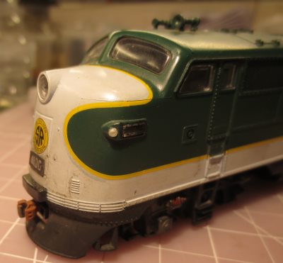
Here's the front end of the same engine with a short shank EC87M040K mounted (available separately). Pretty nice. |
 |