All About Coupling Distance
A very commonly asked question is "Do Prototype Couplers give a prototypical coupling distance?" Unfortunately, there is no easy answer to this question because coupling distance has varied widely on the prototype over the years and is all over the map in the modern era. This page probably contains more than you want to know about the subject, but it does address the issue.
Please Note: I'm no expert on this subject. If you are, and you recognize an obvious untruth in this discusion, please email me. For completeness, this page dicusses makes of couplers other than those manufactured by Prototype Couplers. Prototype Couplers is not affiliated with the makers of these other couplers in any way, and their products' names are registered trademarks of those companys.
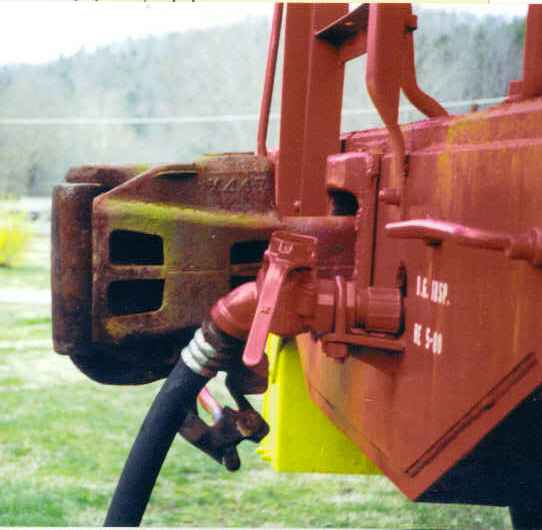
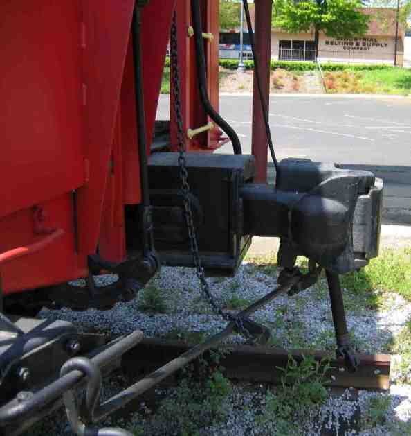
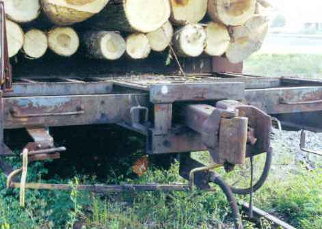
Consider the three photos below. The photo on the left of end of a Southern Railway caboose demonstrates what most consider to be close to the traditional configuration. The center photo is also the end of a caboose on display; this time a Norfolk and Western version. The photo on the right is the end of GPSX log rack. You can see that each of these configurations will produce very different coupling distances.
 |
 |
 |
 |
Mounted to the end of what we modelers call a "draft gear box", is a striker plate (or striker casting in earlier years). When an engineer slams a train together, the couplers get shoved back into the "draft gear box". If the hitch is really rough, the coupler head will get shoved all the way back to bump up against the striker, which explains how the striker got its name. You can easily identify the strikers in the photos above.
Notice that in the case of the Southern caboose, the striker plate is right up against the end sill. In the case of the N&W caboose, the striker is moved out from the cars end sill a bit. In the case of the log rack, the striker is moved way out. A similar observation can be made about the distance the coupler is from the striker.
Understanding the function of the draft gear helps to explain why car builder might desire more room for the draft gear by extending the "draft gear box". It also helps to explain why a car builder might want to allow more movement of the coupler in and out of the box by increasing the distance between the coupler head and the striker. The term "draft gear" refers to the shock absorbing mechanism that connects the coupler to the center sill of the train car. The design of prototype draft gear is a science. Draft gear that is too stiff causes unnecessary wear and tear on the cars because it won't absorb the shock as the train gets repeatably stretched and slacked. Draft gear that is too soft, will do the same if the couplers end up "bottoming out" against the strikers. In the days of roofwalks and brakemen that had to jump between cars on a moving train, there was a very good reason to limit coupling distance at the expense of optimum shock absorption by the draft gear. In the modern era, that concern has disappeared. Is it any wonder then, why in the photos above, the car with the coupler sticking out the farthest is also the most modern?
What we refer to simply as coupling distance is made up of three different measurements. These are, (A) the distance from the end sill of the car to the striker face, (B) the distance from the striker to the rear of the coupler head, and (C) the distance from the coupler head to the midpoint of two connected couplers. This is illustrated below:
The distance (A) varies on the prototype in the modern era as shown by the photos above, but much less so over the course of the steam era since it was important to minimize the coupling distance for the safety of the brakemen. During the steam era, the striker was more often a casting than a plate. The details of the casting appear to vary wildly, but the distance was generally around 8". Most models reproduce this measurement fairly accurately -- even if the width of the casting is greatly exaggerated to allow increased swing of the coupler on our tighter than prototype curves. The model striker plates that are molded as an integral part of a draft gear box supplied with a package of couplers are rarely accurate. Compare the strikers molded on the opening of these draft gear boxes with any of the photos above and you'll understand what I mean. The only exception to this rule appears to be the Accurail Proto:HO draft gear box.
The distance (B) varies on the prototype in much the same was as the (A) distance. The exact measurement is determined by the draft gear design. For steam era modelers, this distance is generally between 3" and 4.5". On our models, the (B) distance is determined by the length of the coupler shank and the location of the coupler mounting post or screw hole. As modelers, we are lucky in that it is possible to relocate a coupler mounting post to obtain whatever (B) distance required by our particular prototype. We would be even luckier if the coupler shank length were such that we didn't have to move the mounting post.
The distance (C) is 12" on the prototype for both AAR type D and type E couplers. The Prototype Couplers coupler faithfully reproduces this measurement. This distance is very difficult to determine for more traditional model couplers because of the slop introduced by the design as the couplers are stretched and compressed.
So now we return to the original question...
"Do Prototype Couplers give a prototypical coupling distance?"
It should be obvious at this point that the real answer depends on the particular prototype and the location of the coupler mounting post / screw hole. BUT, that's probably not the answer you were looking for. What you really want to know is how does coupling distance compare with other makes of couplers. Here's a table that shows length from the center of the mounting posts as measured on a random pair of like couplers.
| Type | Mounting Post Center to Center | Slop | |
| Fully Stretched | Fully Compressed | ||
| Prototype Couplers EC87 | 0.887" | 0.877" | 0.010" |
| EC87DC Dummy | 0.880" | 0.861" | 0.019" |
| Accumate® | 0.953" | 0.901" | 0.052" |
| KD #58 | 0.940" | 0.890" | 0.050" |
| KD #78 | 1.040" | 0.985" | 0.055" |
| KD #5 | 0.957" | 0.895" | 0.062" |
Realize that (except for the slop values) no number in this table is any better, or any more prototypical, than any other number. Prototype couplers don't even have mounting post! What this table does do is show what will happen to coupling distance when you replace an existing coupler with another make -- without moving the mounting post. As an example, you can see that if you replace an Accumate® with an EC87, the stretched coupling distance will be reduced by 0.066" (or about 6 scale inches). Whether that happens to be good or bad again depends on the prototype and the location of the mounting post.
Note that the Accurail Proto:HO and Sergent Engineering EN87 couplers are not included in this table because installing these generally requires drilling holes, and if the holes are in the put in the right place you can always obtain the prototypical coupling distance!