Assembly Instructions - ET1P87K
This webpage serves as assembly instructions for Prototype Coupler's Tailor Made BLI Steam Pilot Couplers. No printed instructions are provided with the kits. These are investment cast so you should familiarize yourself on the extra steps required here. You'll see that assembly of these couplers is simple and similar to the EC87 couplers as well. This has been tested with BLI Paragon4 UP Big Boy, and BLI Paragon4 UP FEF-3. This may fit other BLI Locomotives but are untested by Prototype Couplers.
|
These instructions cover the assembly of our Tailor Made Broadway Limited Imports Steam Pilot. |
 |
|
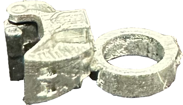
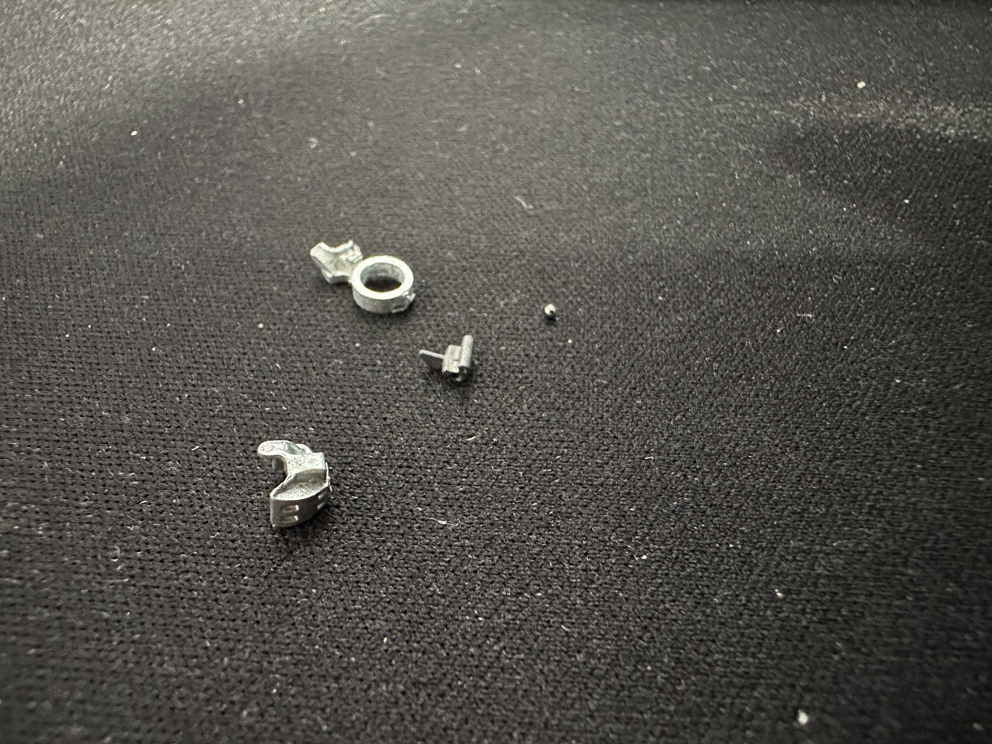
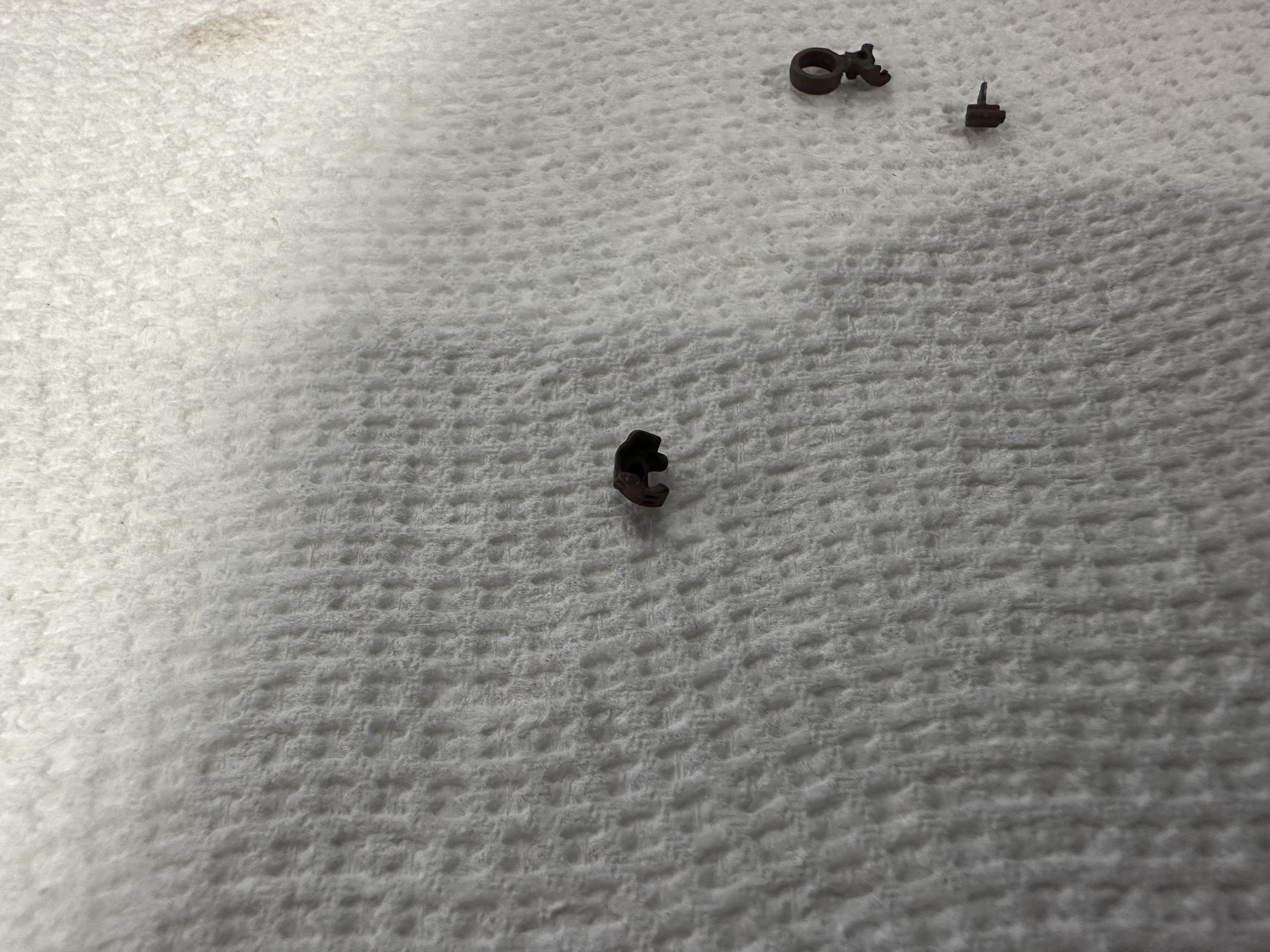
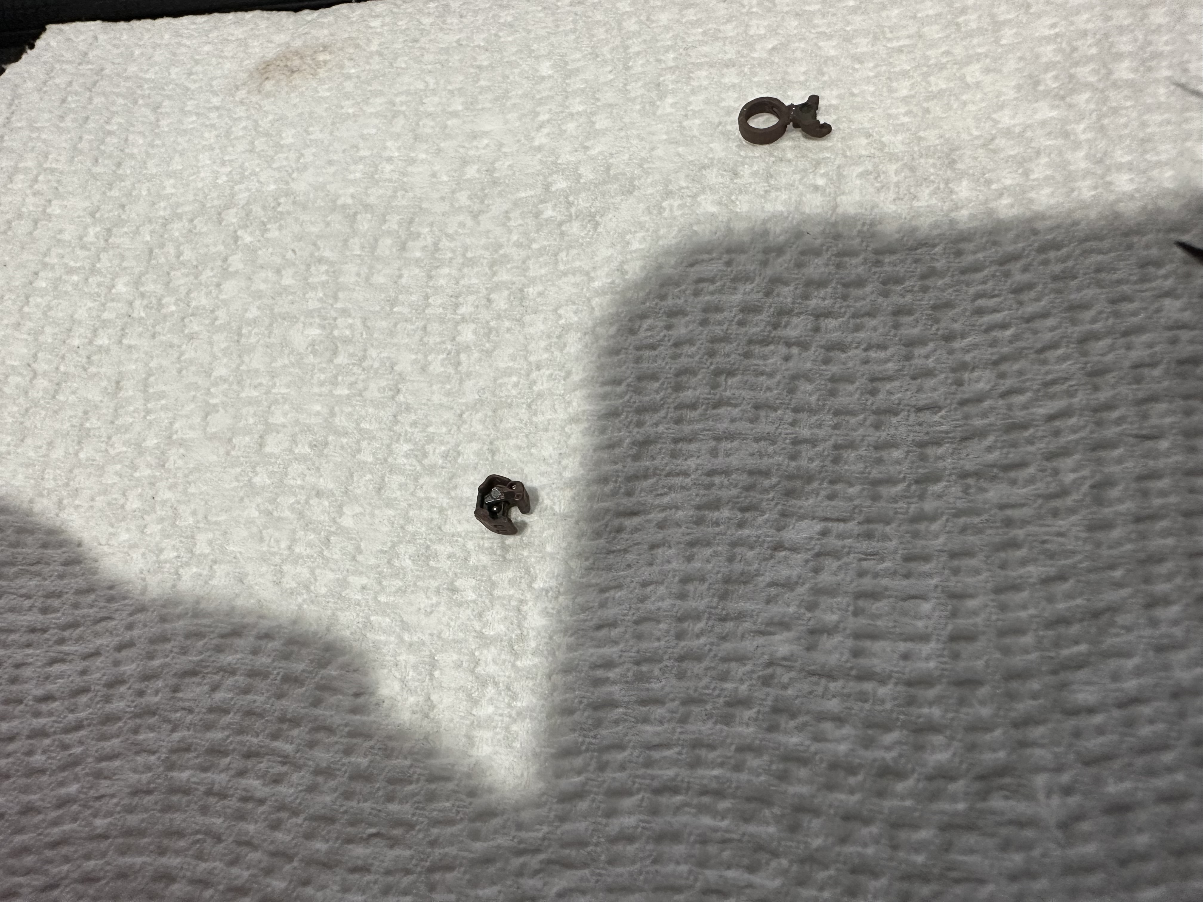
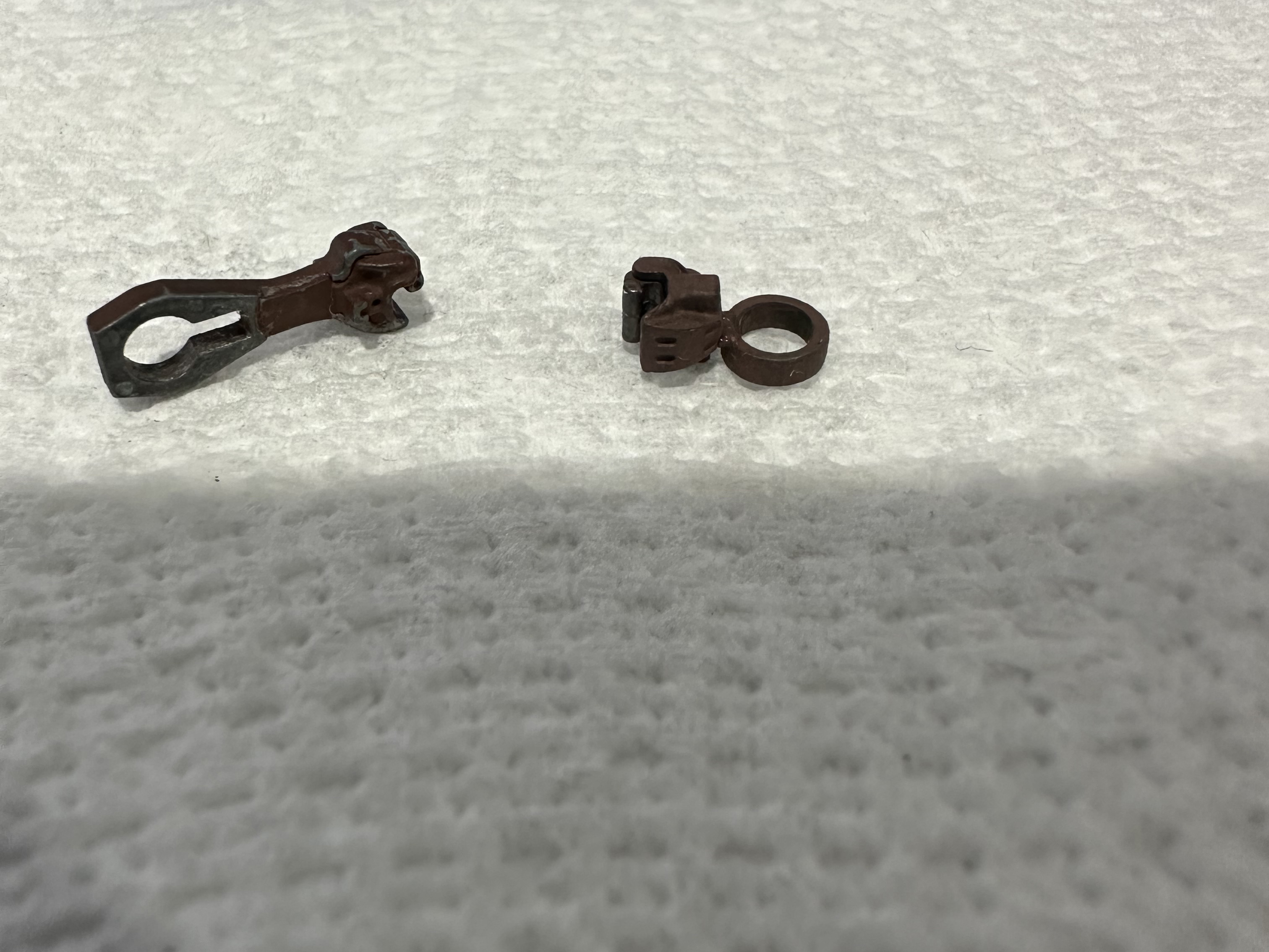
This is what comes in your kit, 1 Top Casting, 1 Bottom Cover Casting, 1 Knuckle Casting, and 1 Ball. |
 |
|
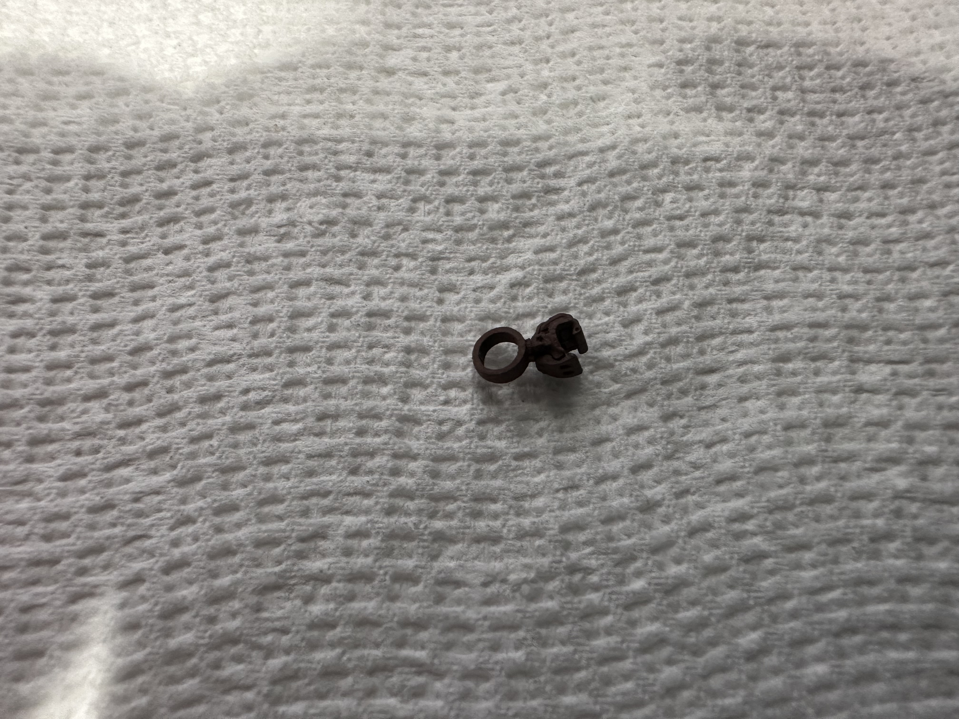
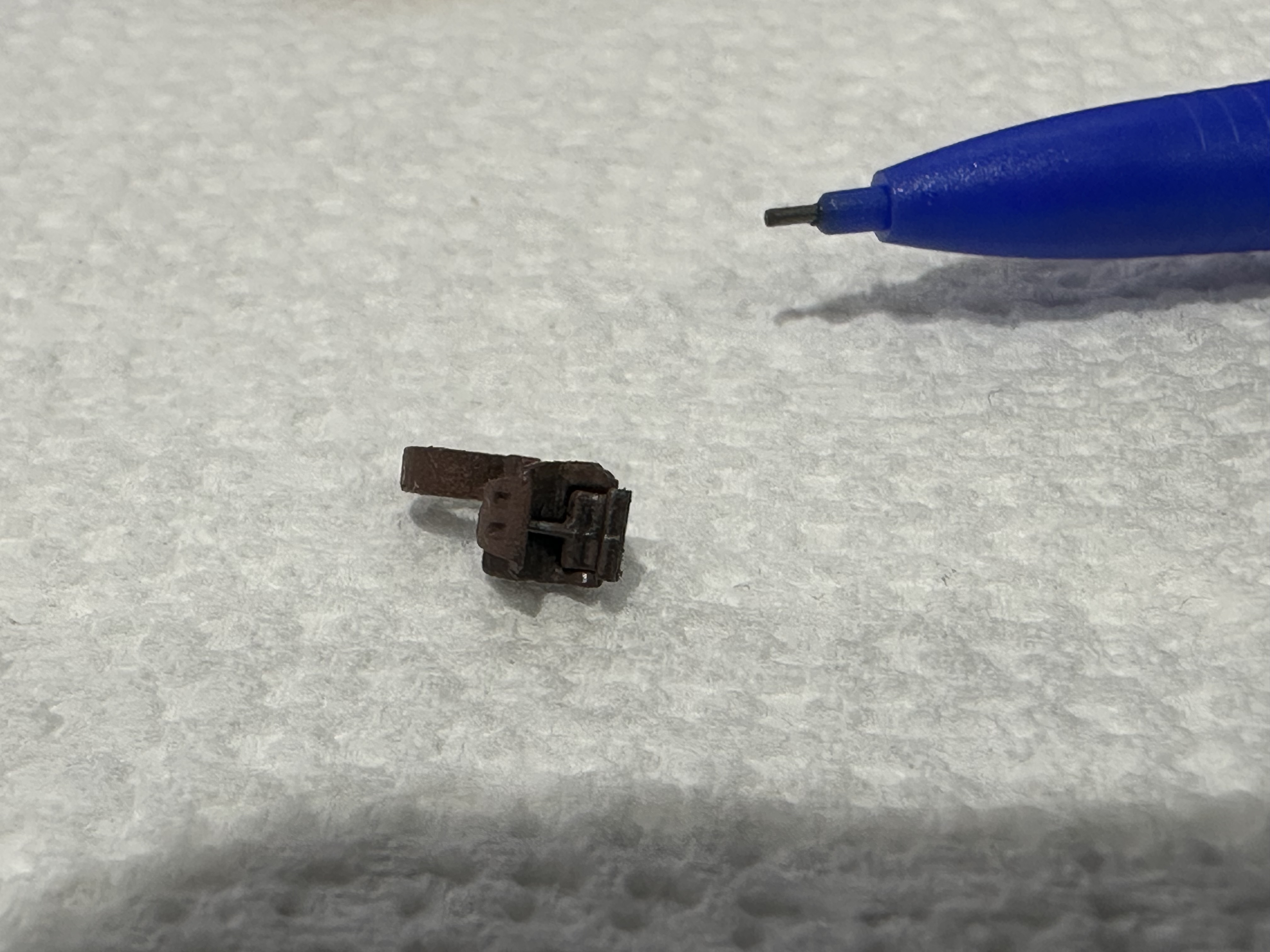
The Castings will need some sanding/filing in a few key spots. Right behind the coupler head where the shank would normally be on an EC87K. Also, where the bottom cover is broken off the sprue at the rear of the ring. |
  |
|
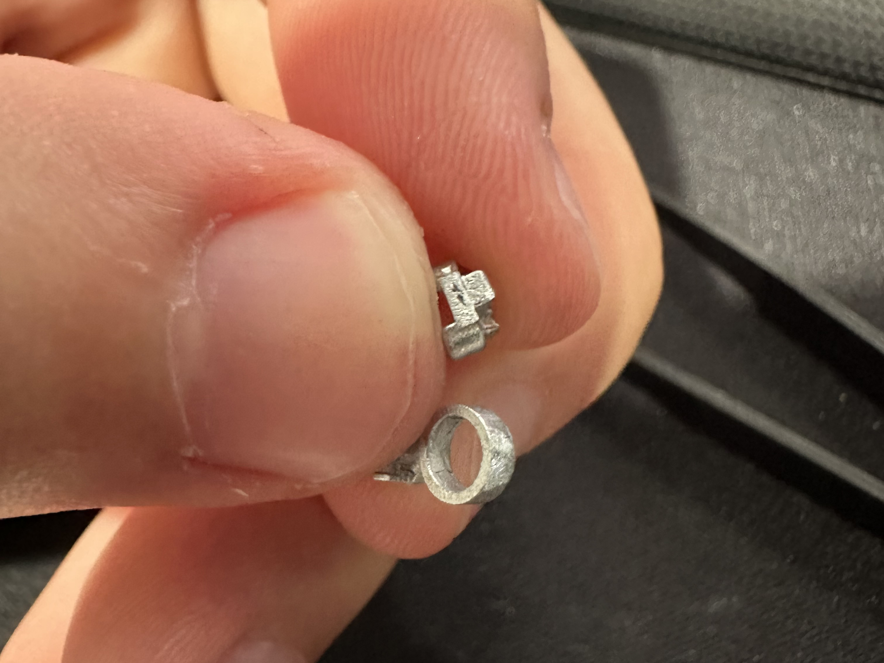
The castings will need to be painted prior to assembly and prior to painting it’s a good idea to inspect the castings for flash. The photo indicates potential locations where top and bottom castings should be inspected for flash. The flash is easy to remove with a hobby knife. In the case of the knuckle, you won't find much flash, but you might find a protrusion on the tip of the knuckle that can prevent reliable coupler locking. This is the location where the knuckle is broken away from its sprue. This can be scraped away with a hobby knife as well. After flash is removed castings should be painted prior to assembly. Let the paint cure for a day or two so it gets hard, then assembly can continue. Notice that only the top side of the coupler casting is painted. Painting the side of the castings where the ball lives not recommended. |
 |
|
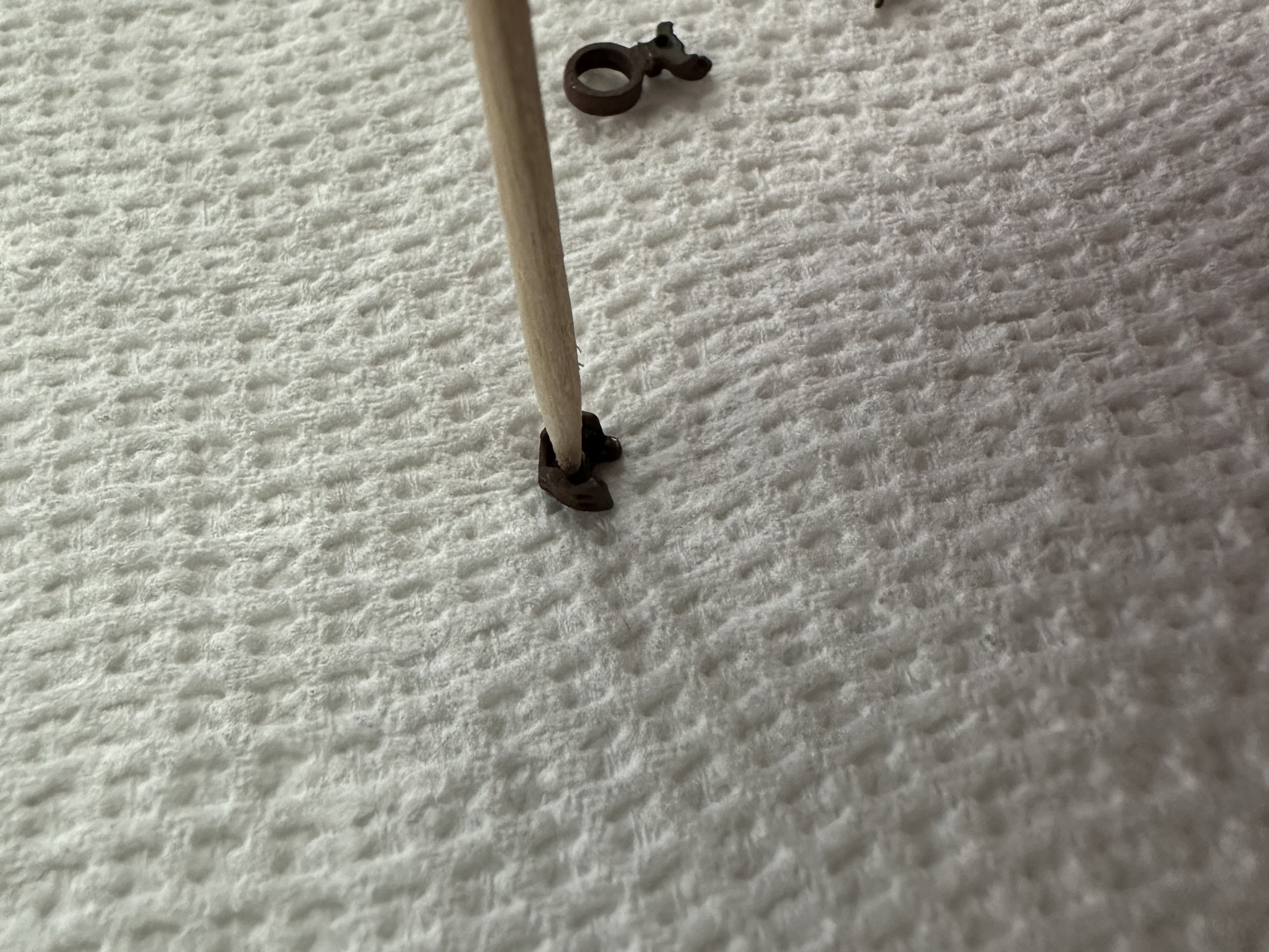
The ball cylinder in the top casting should be cleaned and burnished slightly by spinning a round toothpick in it. Cut the sharp end of the toothpick off so it fits snuggly into the hole and spin. The step reduces the likihood that the ball will stick in the top casting and keep the coupler from reliably locking when coupling. You might also find a bit of a walnut hull lodged in the cylinder. (The castings are tumbled in walnut hulls as part of the manufacturing process.) If so, just pick it out with the tip of a hobby knife. |
 |
|
No fixture is currently available for these. Start by placing the top casing upside down on your work surface. |
 |
|
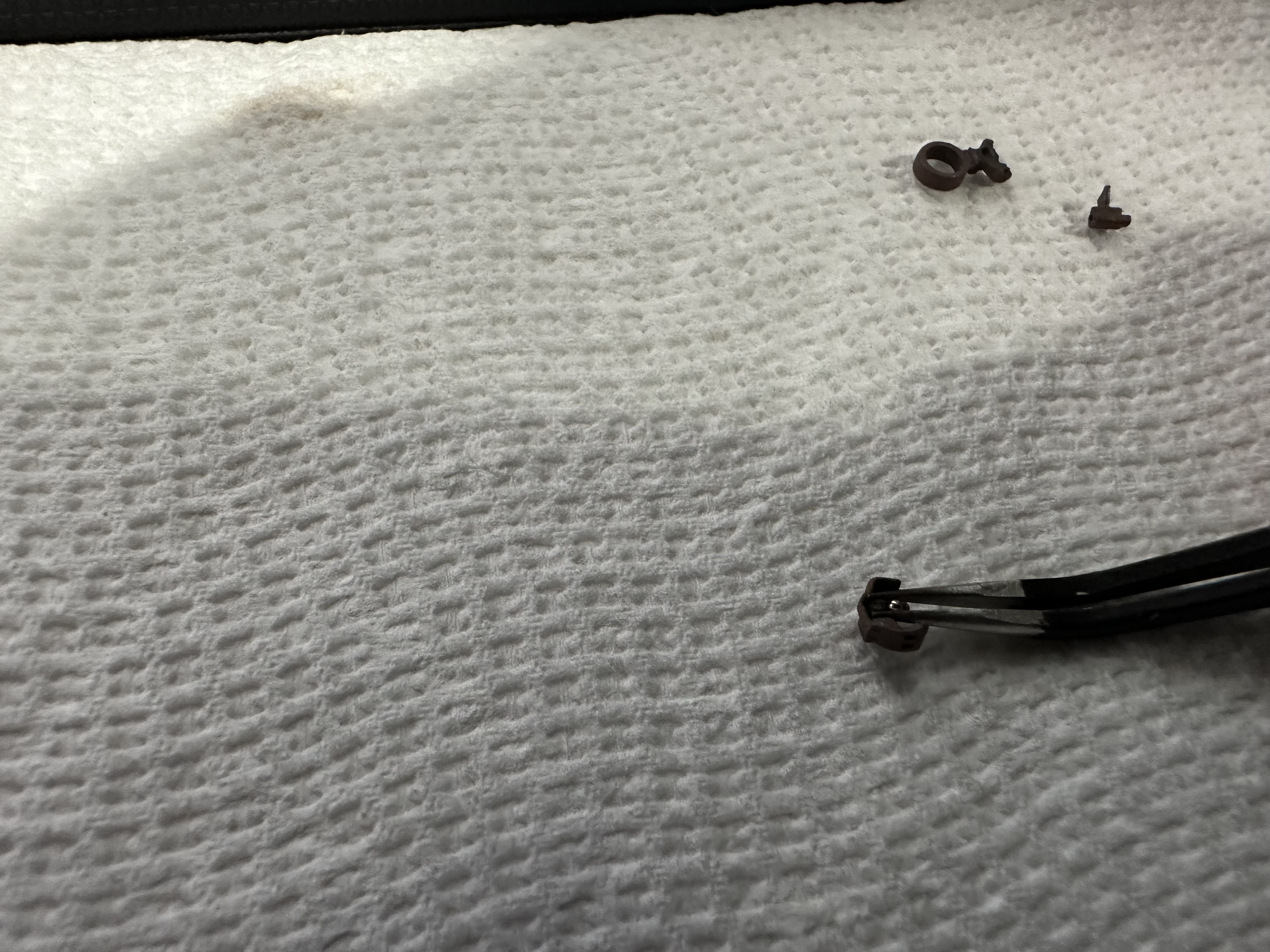
Next, load the ball using tweezers. Don't touch the ball with your bare hands else you might get skin oils on it that might keep it from moving freely. |
 |
|
Load the knuckle next. Tweezers are helpful here as well. You may need to help hold the knuckle in place with your fingers while you drop the bottom on. |
 |
|
Next comes the bottom cover casting. There is no alignment pins on these couplers. Just press the parts together until you have an even fit with the top casting. |
 |
|
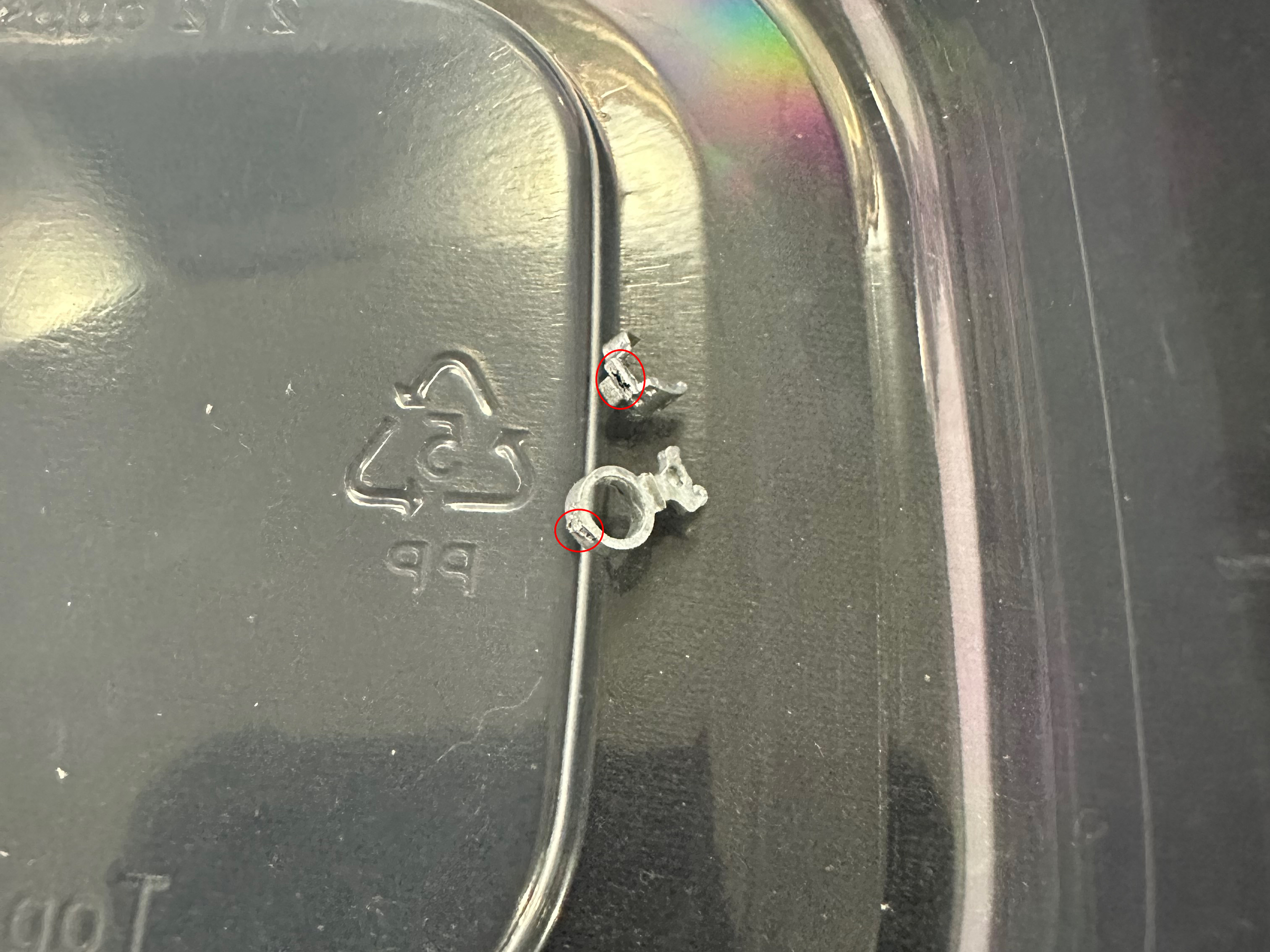
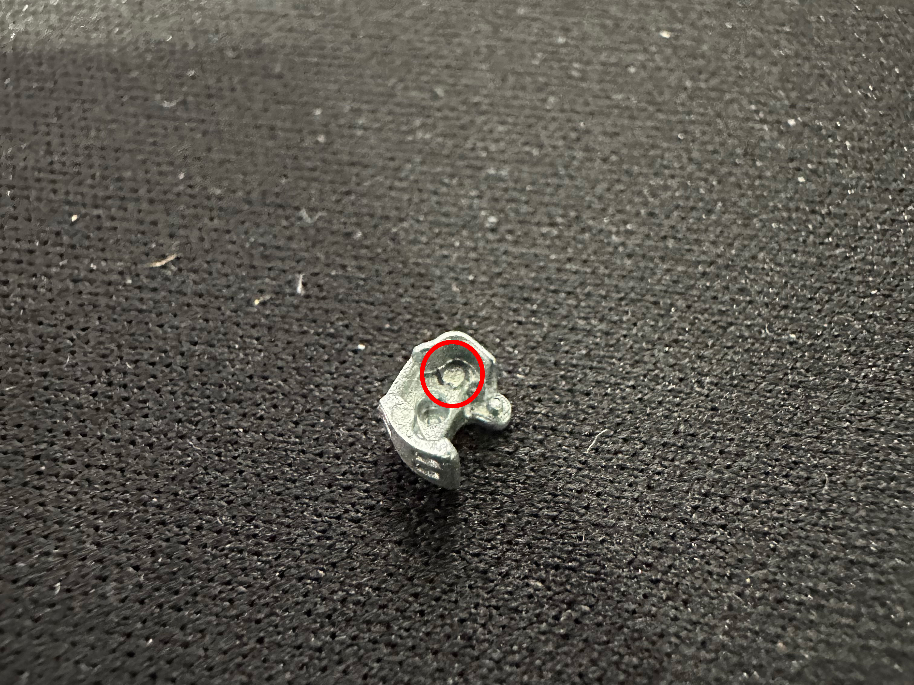
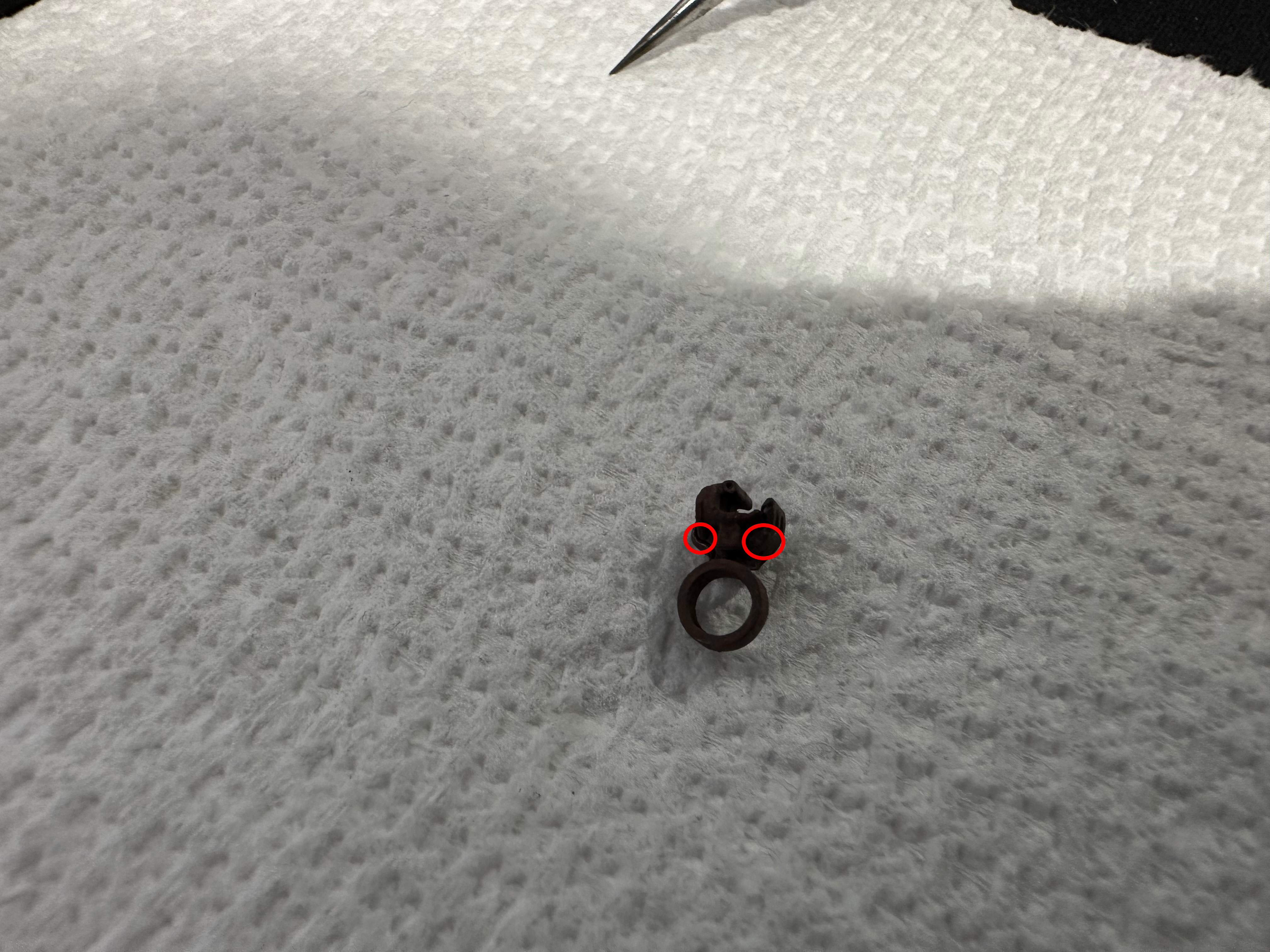
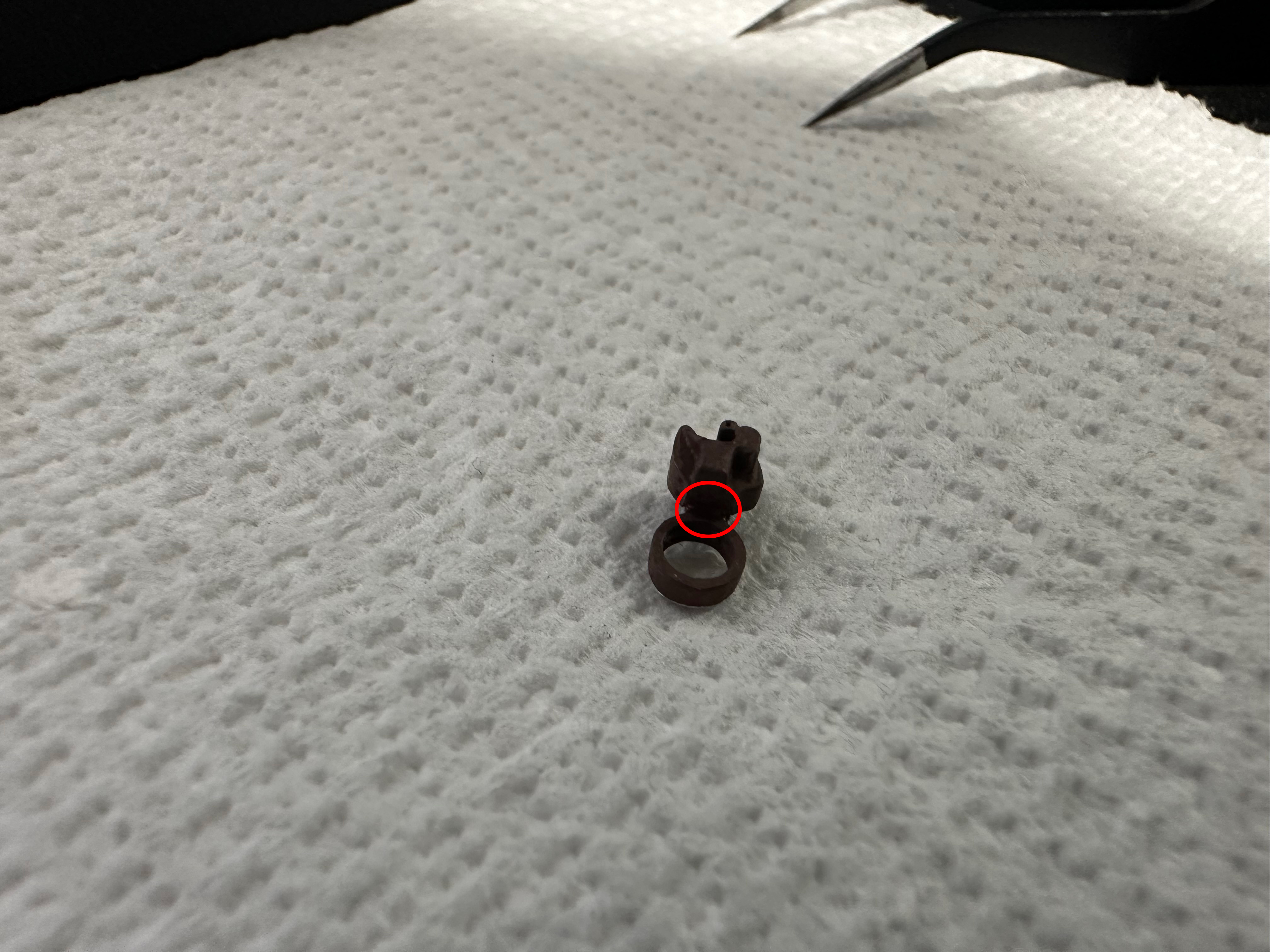
After installing the bottom cover, you must glue the casting. Small amounts of CA glue should be applied to the rear of the coupler head where the bottom and top castings meet, and a tiny dot should also be applied to the head of the coupler where there is a gap between the bottom and top castings as indicated by the red circles. This will prevent the bottom cover from popping off under high stress conditions. Use a toothpick to apply a tiny dot of gap filling CA at the points indicated by the red circles in the photo. We use Zap-A-Gap which is available from MicroMark. We don't recommend the extra thick gel type glues. |
  |
|
Let the glue cure while the coupler is still UPSIDE-DOWN. If the coupler is turned rightside-up before the glue cures fully, there is a chance that the ball will fall into some glue and the coupler will be locked forever. The "forever" part isn't entirely true. Couplers that are assembled with CA can always be taken apart after soaking them in acetone for about five minutes. Leave the coupler in overnight and all traces of the glue will be gone. Do expect to have to repaint the coupler in this case though. |
|
|
Break-in is essential if the couplers are to operate reliably. Pencil lead (graphite) makes a great lubricant. The first step is to color the mating surfaces thoroughly with a pencil. Be sure the knuckle is covered on both the inside and outside surfaces. |
 |
Once the graphite is applied, you should take a spare coupler and the couplers should be operated by hand while upside-down to allow the graphite to find its way into all the inner workings. This will break loose any flash on the mechanism. |
|
Next, rake the couplers over each other vertically to polish the surfaces and smooth away any potential operational problems. Turn the couplers right side up and let them lock together. Push them together while you slide them across each other vertically to polish the coupler head socket and front of the knuckles. A little bit of a catch is ok as the knuckle parting lines cross. Now pull them apart while performing the same action. This will polish inner side of the knuckle. |
|
|
After the break-in procedure it’s a good idea to test the couplers by hanging an uncoupling tool off a desk lamp. Couple. Uncouple. Repeat. Go through this a few times until you are confident in the reliability of the couplers. |
 |
|
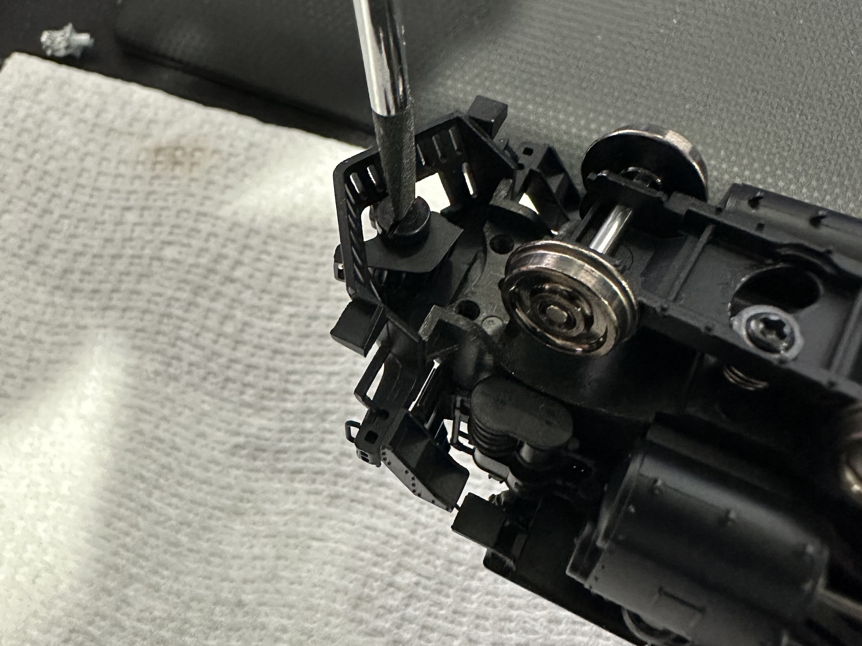
Now we can move on to installing the coupler. First you must take the dummy pilot out of the locomotive. This can be achieved by flipping the locomotive upside down and removing the screw at the pilot. The whole assembly should come right out. I recommend disconnecting the locomotive from the tender if applicable to minimize damage risk. |
 |
|
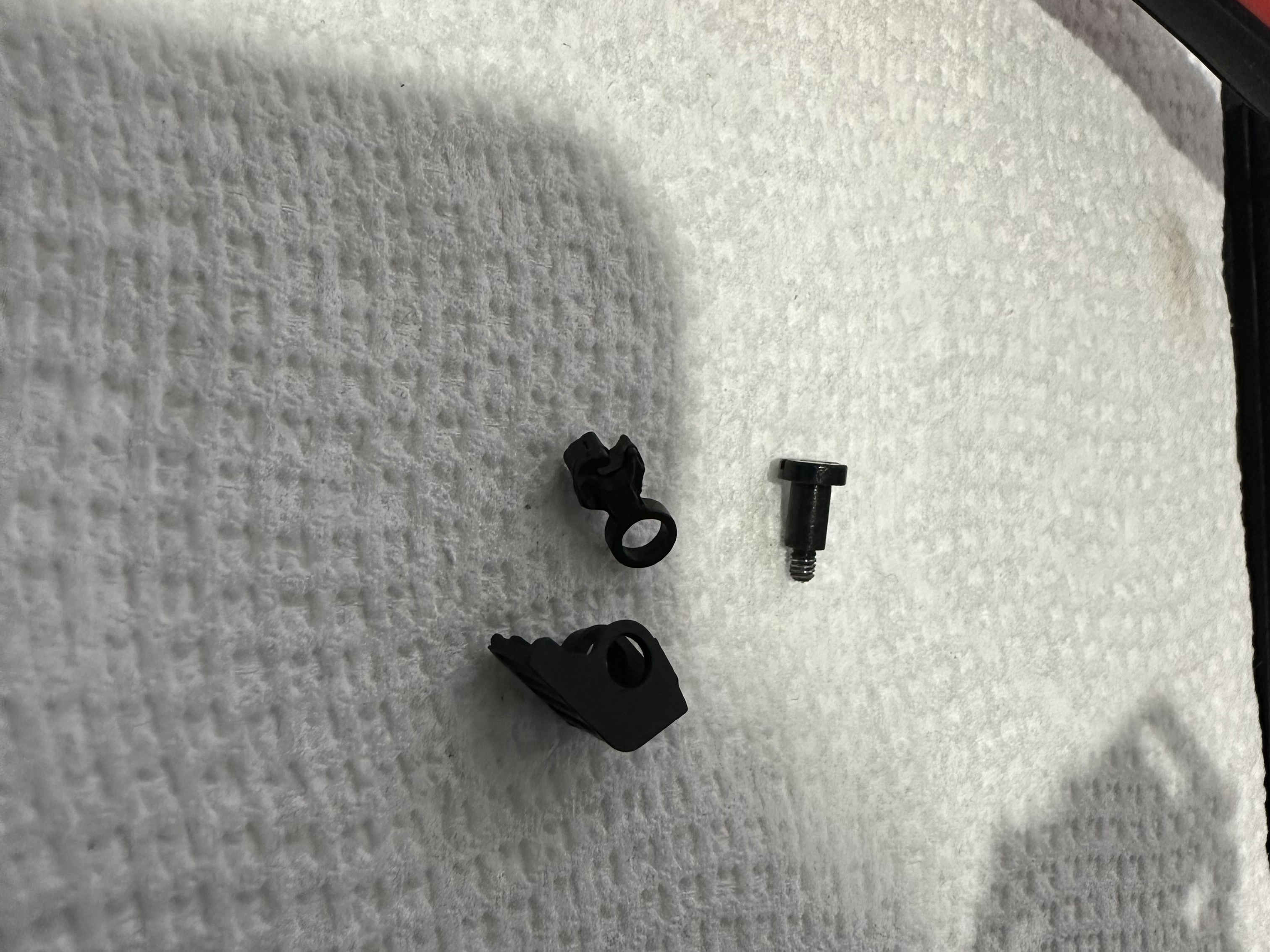
Next separate the dummy coupler from the front plow door. |
 |
|
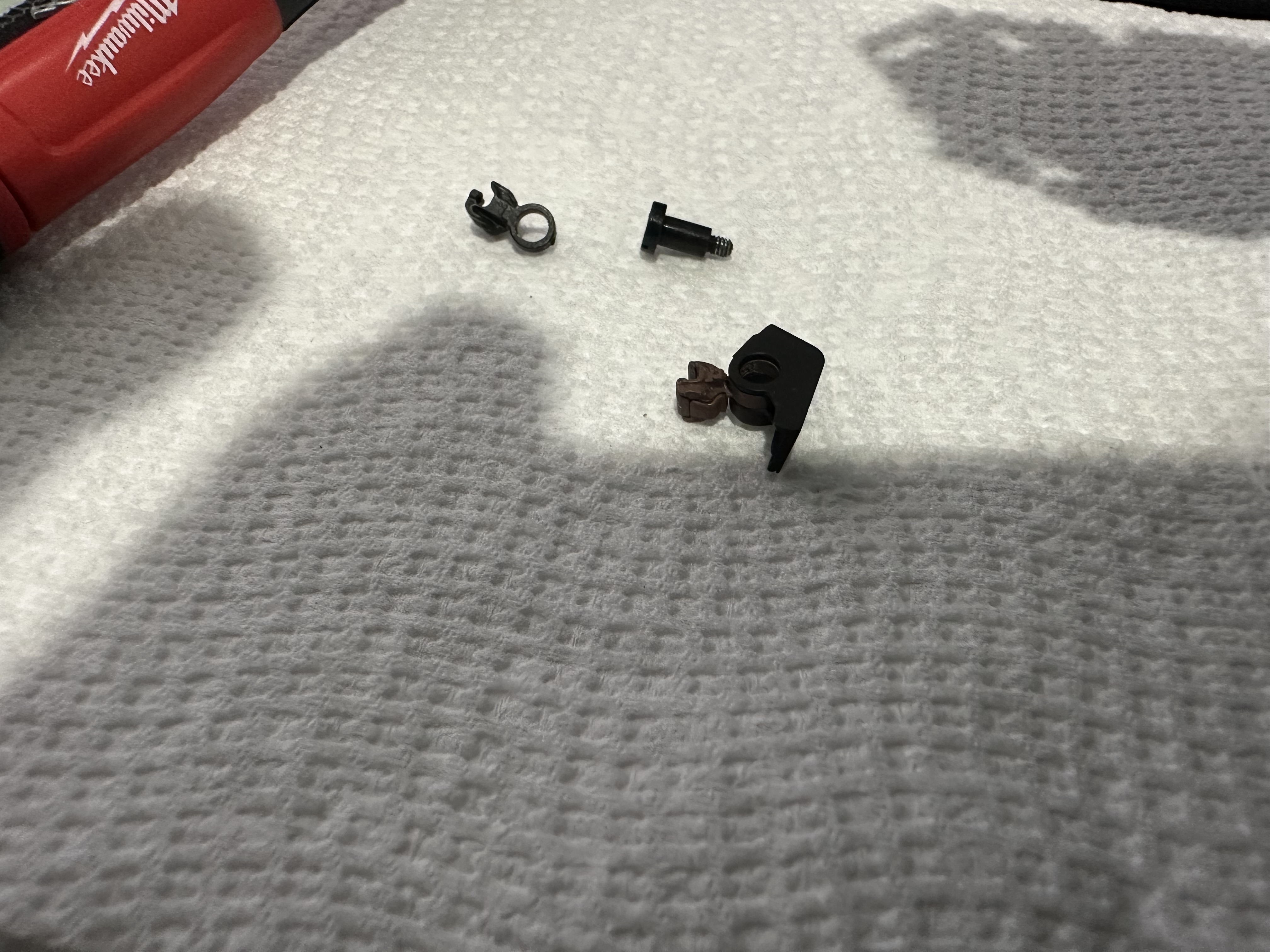
Then you can place your new functional scale coupler in its place, making sure you have the orientation the right way. |
 |
|
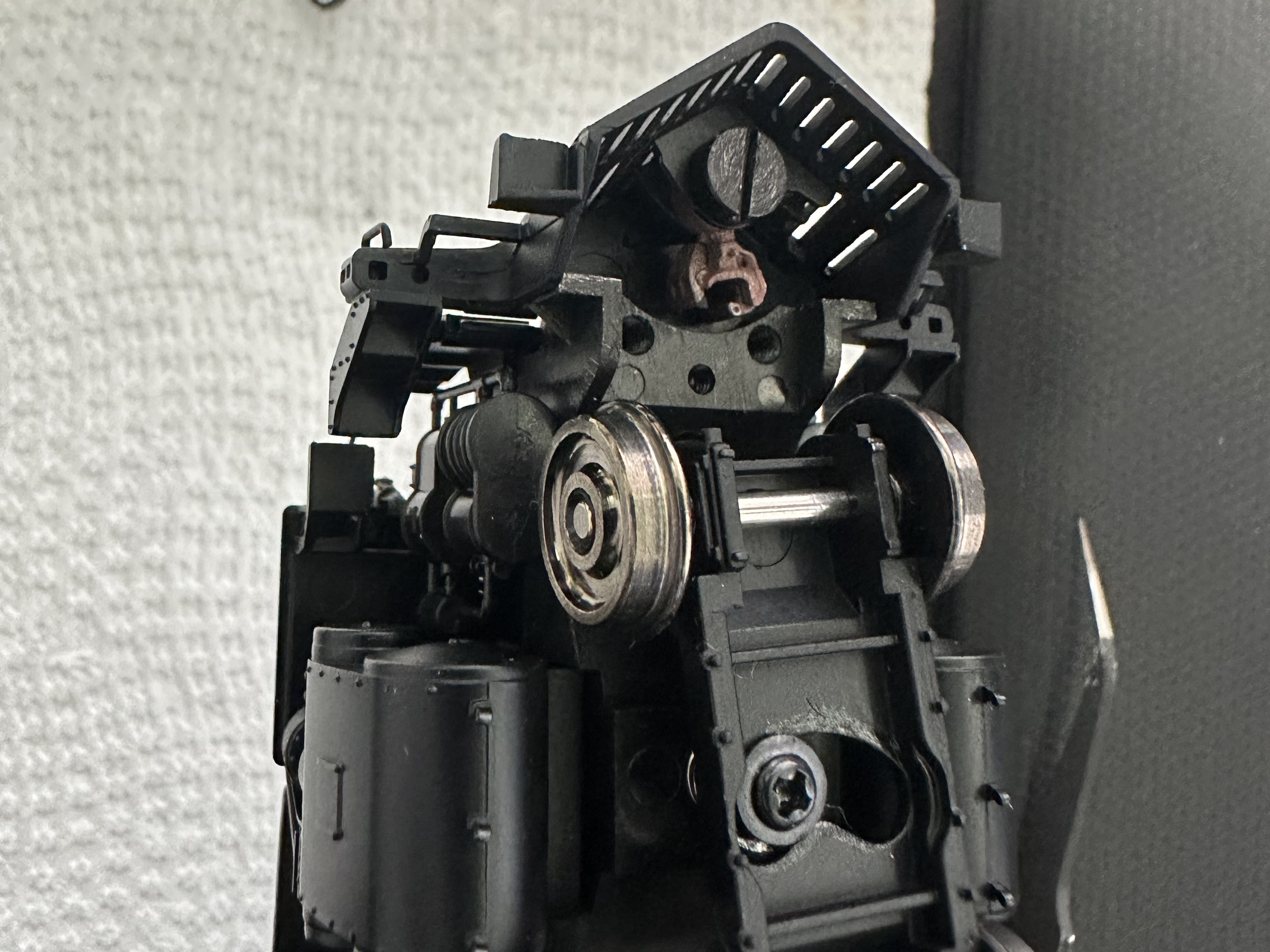
Now you can reinstall the pilot assembly. |
 |
|
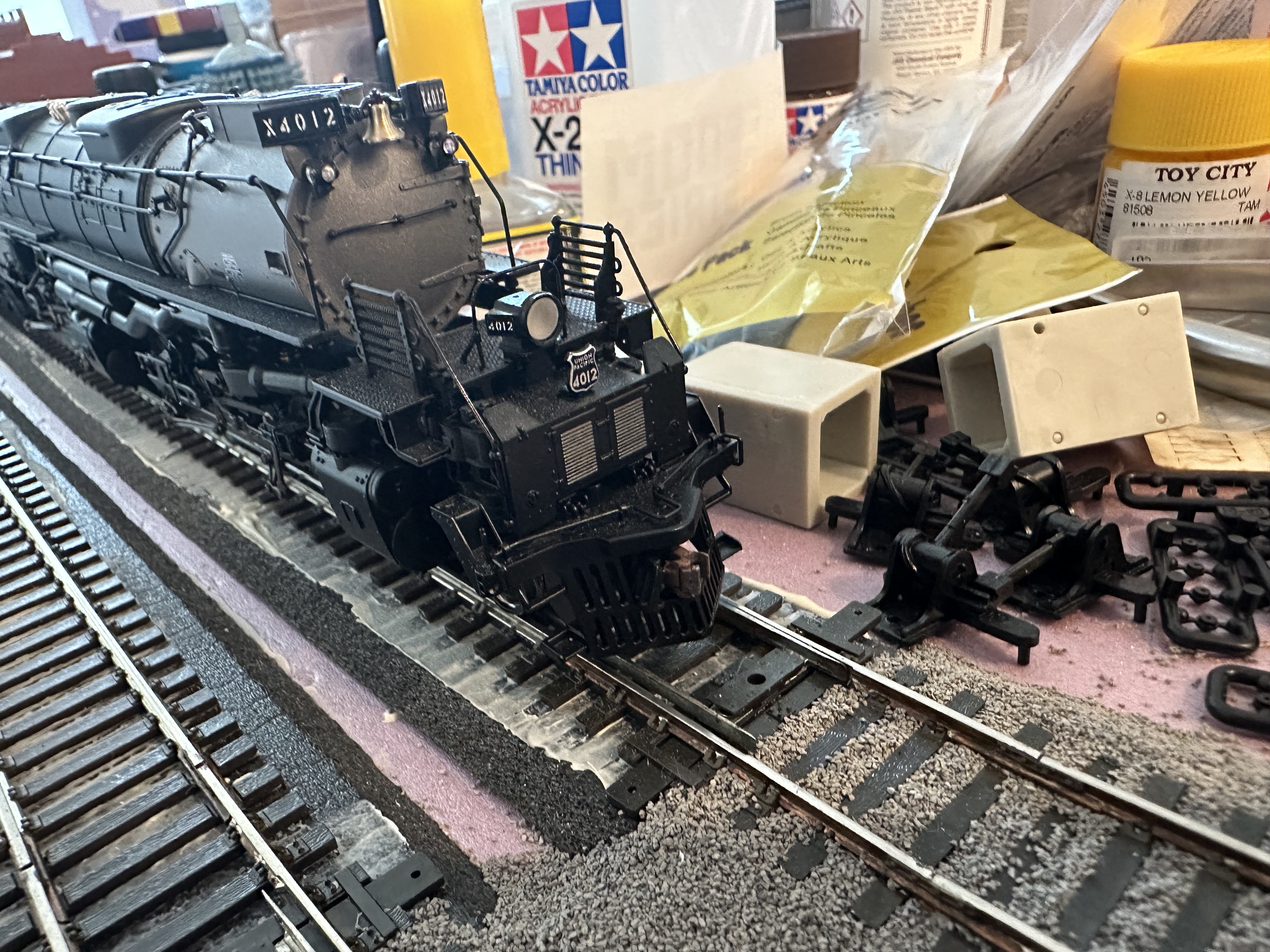
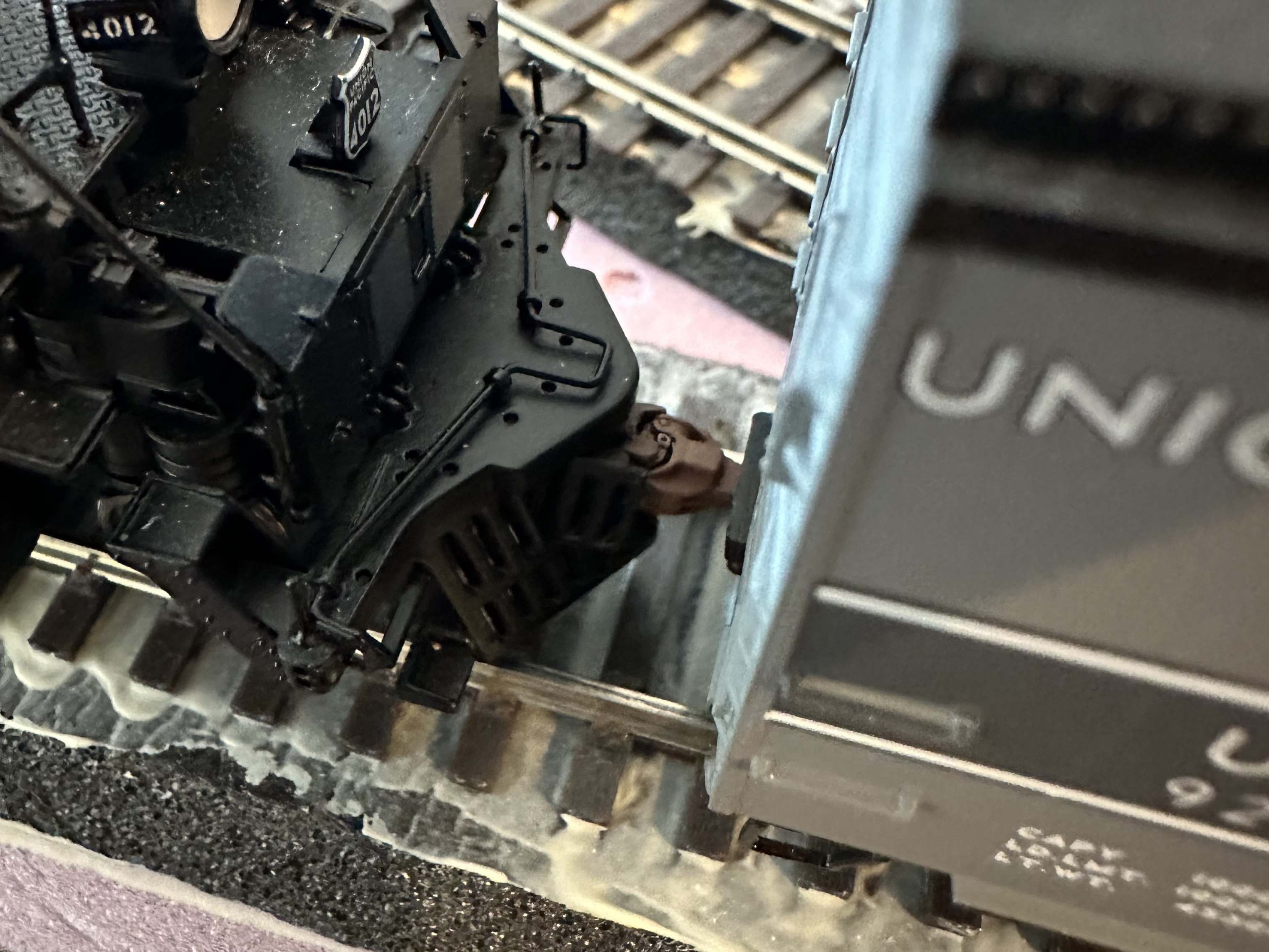
Your new functional front pilot should be ready for use. It retains the same features the factory coupler had, where you can flip between the front pilot or cover it, but you can obviously uncouple and couple this one, useful for multi-unit trains, shunting, or excursion trains. Due to principal flaws in the design of the locomotives themselves, the pilot pivots better in one direction rather than the other. This might make taking corners difficult with this, as far as I can tell this is a flaw of the swinging door mechanism and not the replacement functional pilot. |
  |