Assembly Instructions - RC87K, RN87K, RNB87K, RNC87K
This is a backup of Sergent Engineering's original instructions. I have uploaded some replacement photos that cover most of the actual coupler assembly. There are still missing photos for installing the couplers into draft gear boxes. I do not have any scale draft gear boxes to play with so these will remain missing for the time being.
This webpage serves as assembly instructions for Sergent Engineering Sharon style couplers. No printed instructions are provided with the kits. Like the popular EC87 couplers, the Sharon couplers are diecast. This means castings are very consistant. You'll see that assembly of these couplers is simple and similar to the EC87 couplers as well. Castings that make up the Sharon couplers are tiny so we don't recommend attempting assembly without an assembly fixture.
|
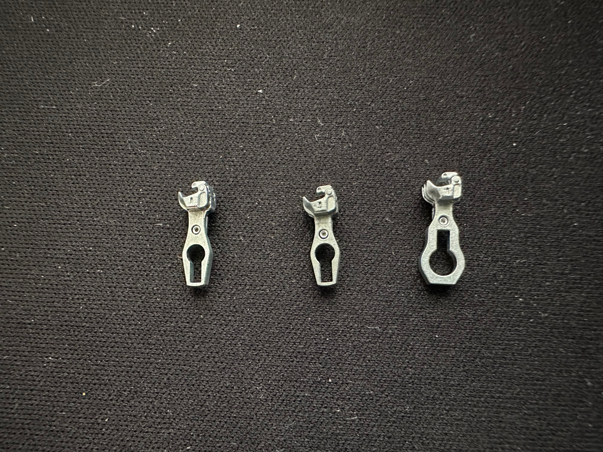
These instructions cover the assembly of all standard flavors of the Sergent Engineering Sharon couplers. Shown in the picture to the right are: (1) the RNC87 narrow shank coupler, (2) the RNB87 which has a slightly shorter narrow shank, and finally (3) the compatible shank RC87. |
 |
|
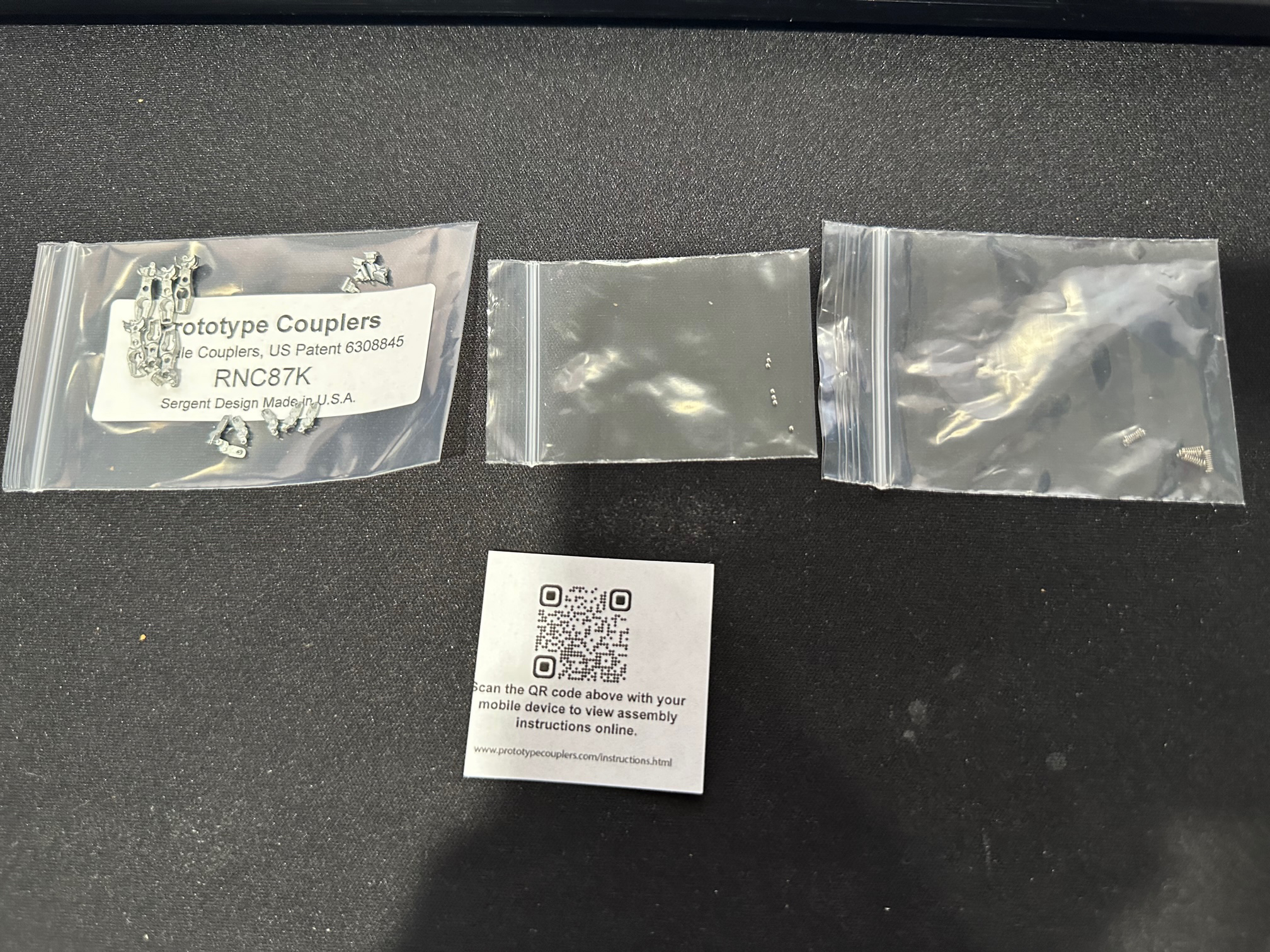
Here is what you will see when you open the kit: top castings, bottom cover castings, knuckle castings, and a ball/spring pack. CAUTION: THE BALL/SPRING PACK FOR THE SHARON COUPLERS IS DIFFERENT FROM THE PACK FOR THE ARA STYLE COUPLERS. While the balls are the same, the springs for the Sharon couplers are much lighter to allow the couplers to easily move during coupling. Coupling won't be reliable if you use the stiff springs with the Sharon couplers. The RN87K additionally contains draft gear boxes and mounting screws. |
 |
|
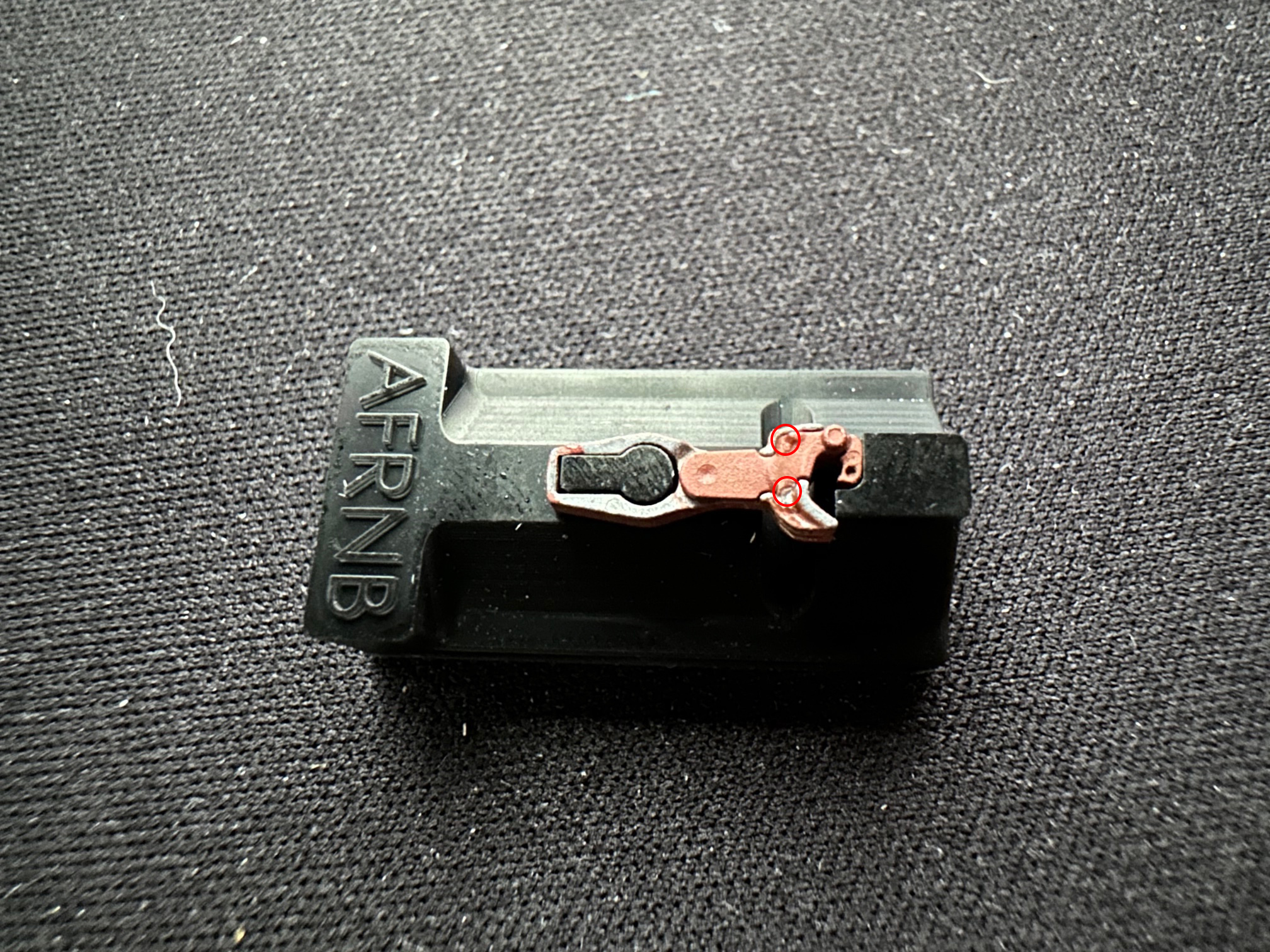
The castings will need to be painted prior to assembly and prior to painting its a good idea to inspect the castings for flash. The photo indicates potential locations where top and bottom castings should be inspected for flash. The flash is easy to remove with a hobby knife. In the case of the knuckle, you won't find much flash, but you might find a protrusion on the tip of the knuckle that can prevent reliable coupler locking. This is the location where the knuckle is broken away from its sprue. This can be scraped away with a hobby knife as well. After flash is removed castings should be painted prior to assembly. |
 |
|
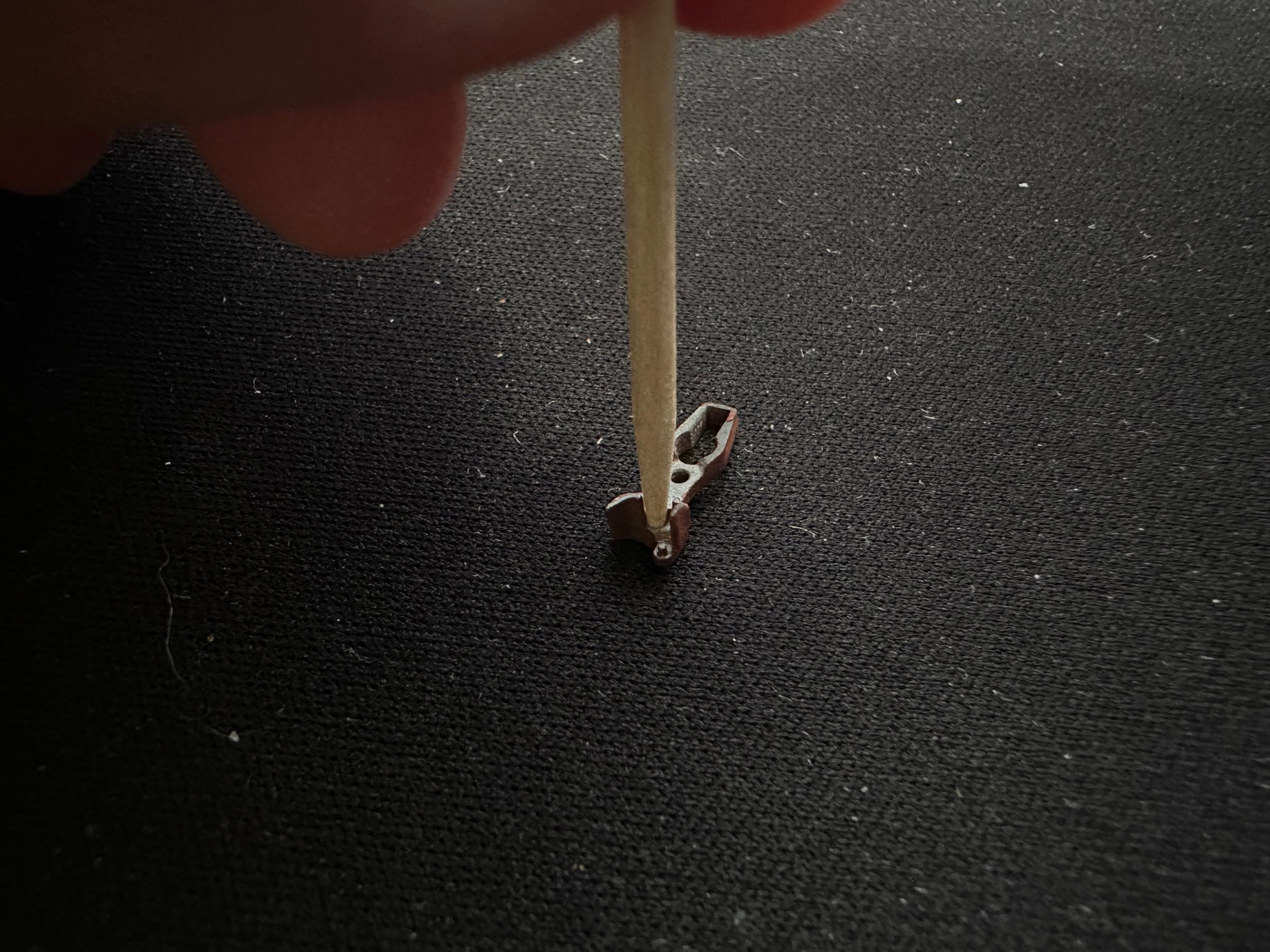
Let the paint cure for a day or two so it gets hard, then assembly can continue. Notice that only the top side of the coupler casting is painted. Painting the side of the castings where the ball lives not recommended. The ball cylinder in the top casting should be cleaned and burnished slightly by spinning a round toothpick in it. Cut the sharp end of the toothpick off so it fits snuggly into the hole and spin. The step reduces the likihood that the ball will stick in the top casting and keep the coupler from reliably locking when coupling. You might also find a bit of a walnut hull lodged in the cylinder. (The castings are tumbled in walnut hulls as part of the manufacturing process.) If so, just pick it out with the tip of a hobby knife. |
 |
|
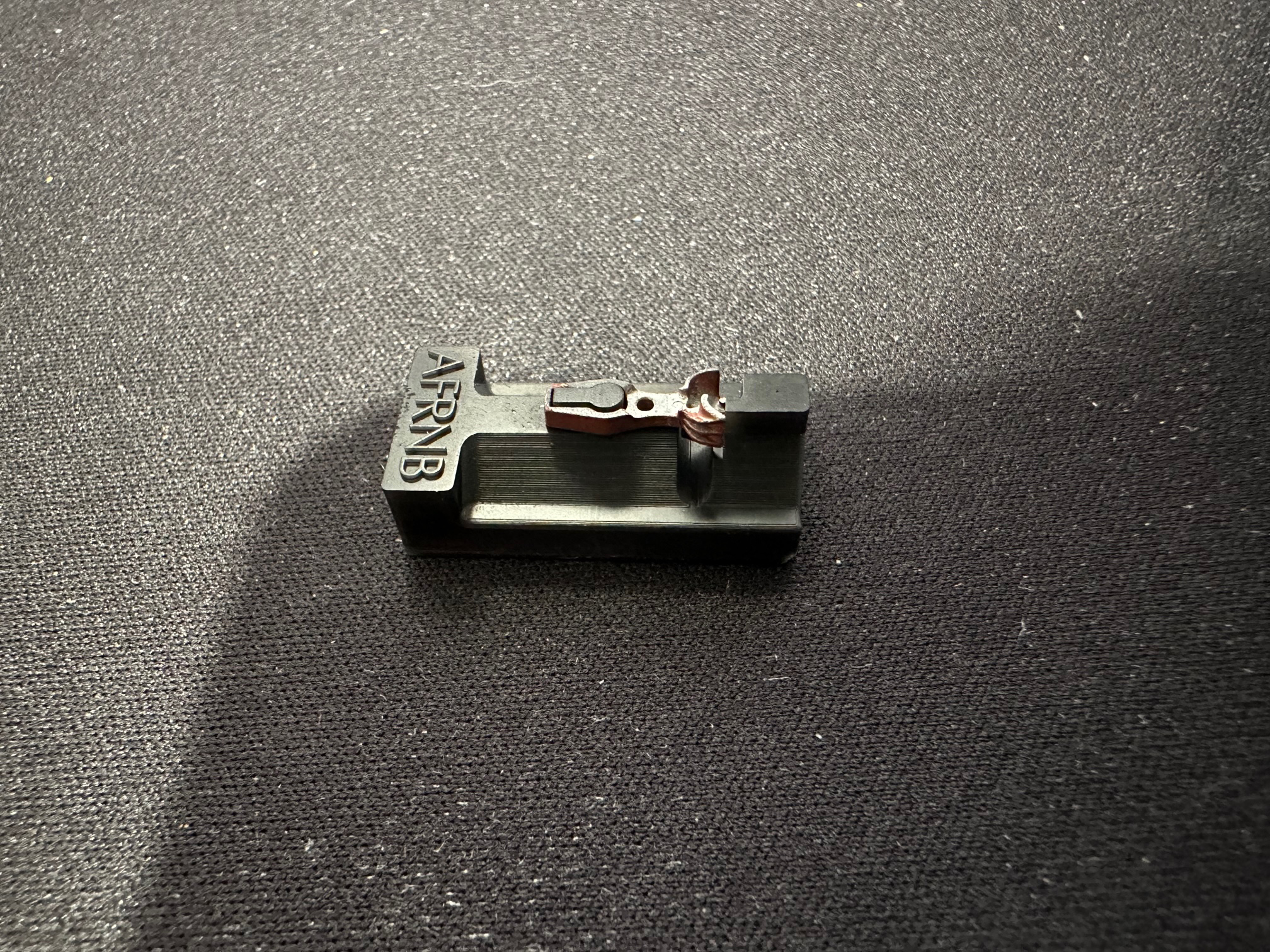
Trying to put lots of these small couplers together without an assembly fixture will drive you nuts. All of our Sharon coupler styles require their own assembly fixture. Start by loading the top casting onto the fixture. |
 |
|
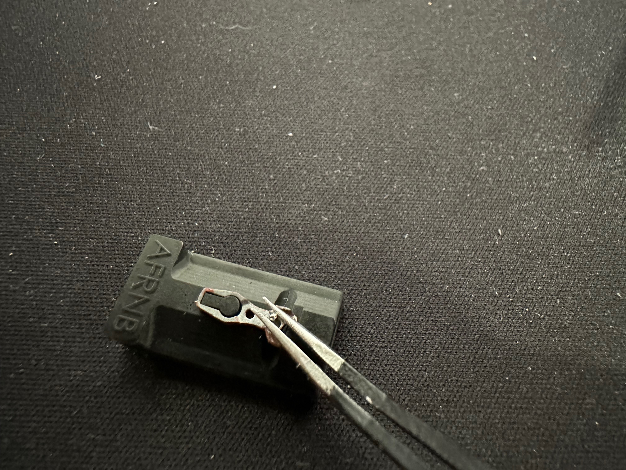
Next, load the ball using tweezers. Don't touch the ball with your bare hands else you might get skin oils on it that might keep it from moving freely. |
 |
|
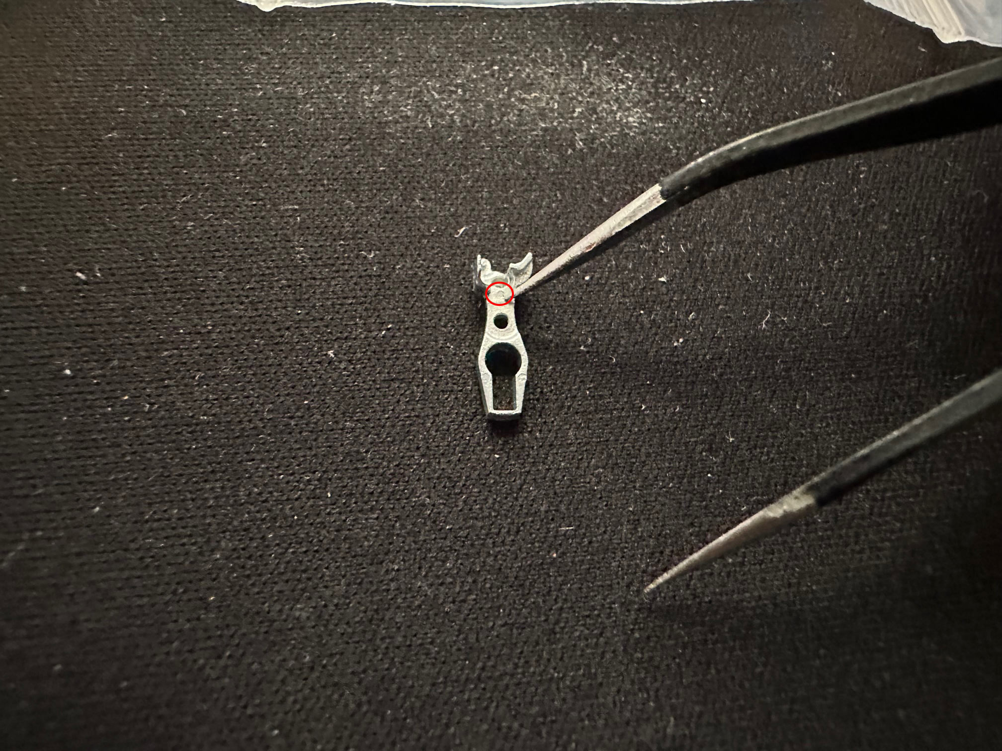
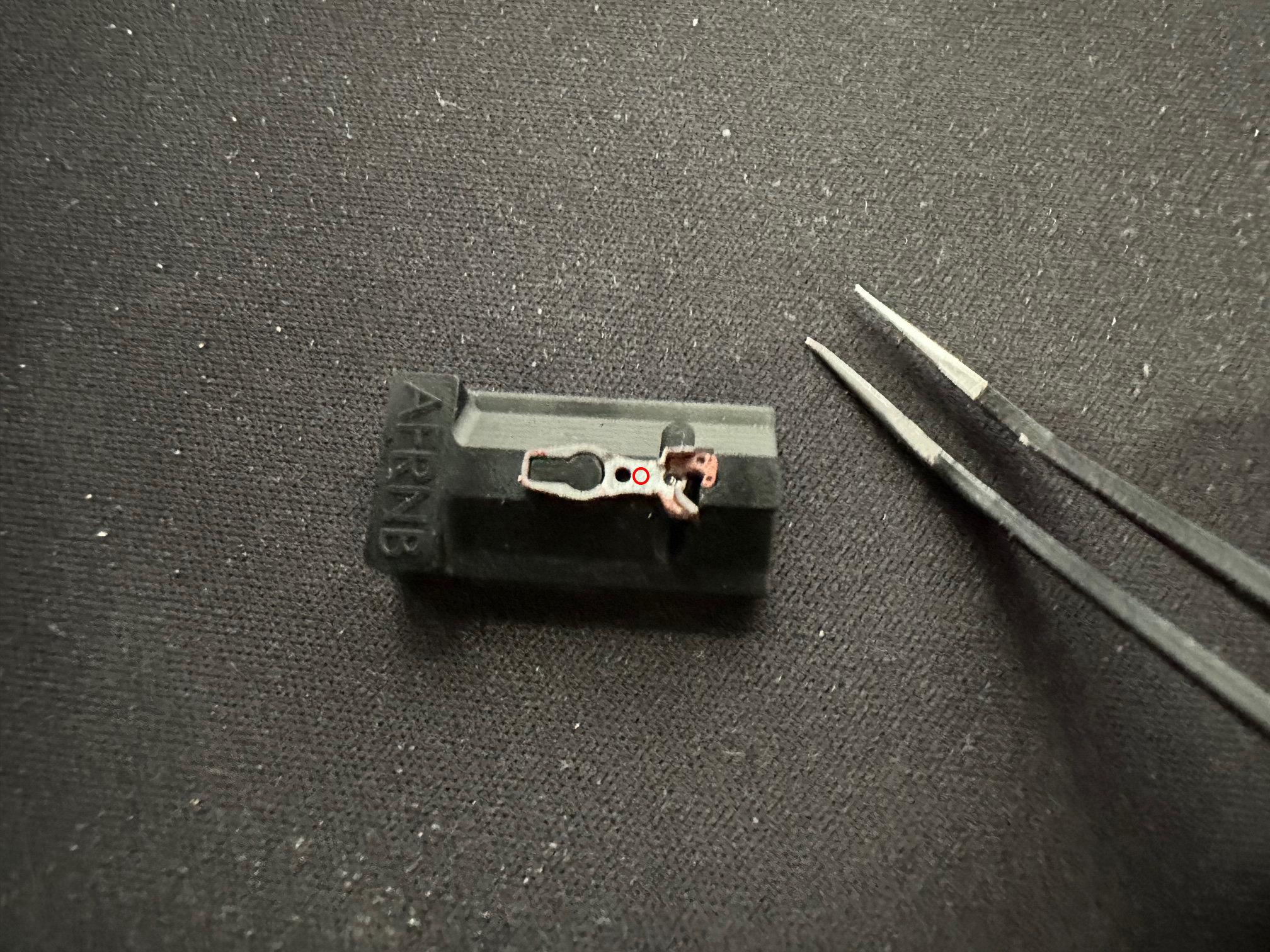
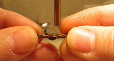
Load the knuckle next. Tweezers are helpful here as well. The assembly fixture will hold it in place once it's in position. Use a toothpick to apply a tiny dot of gap filling CA at the point indicated by the red line in the photo. We use Zap-A-Gap which is available from MicroMark. We don't recommend the extra thick gel type glues. |
 |
|
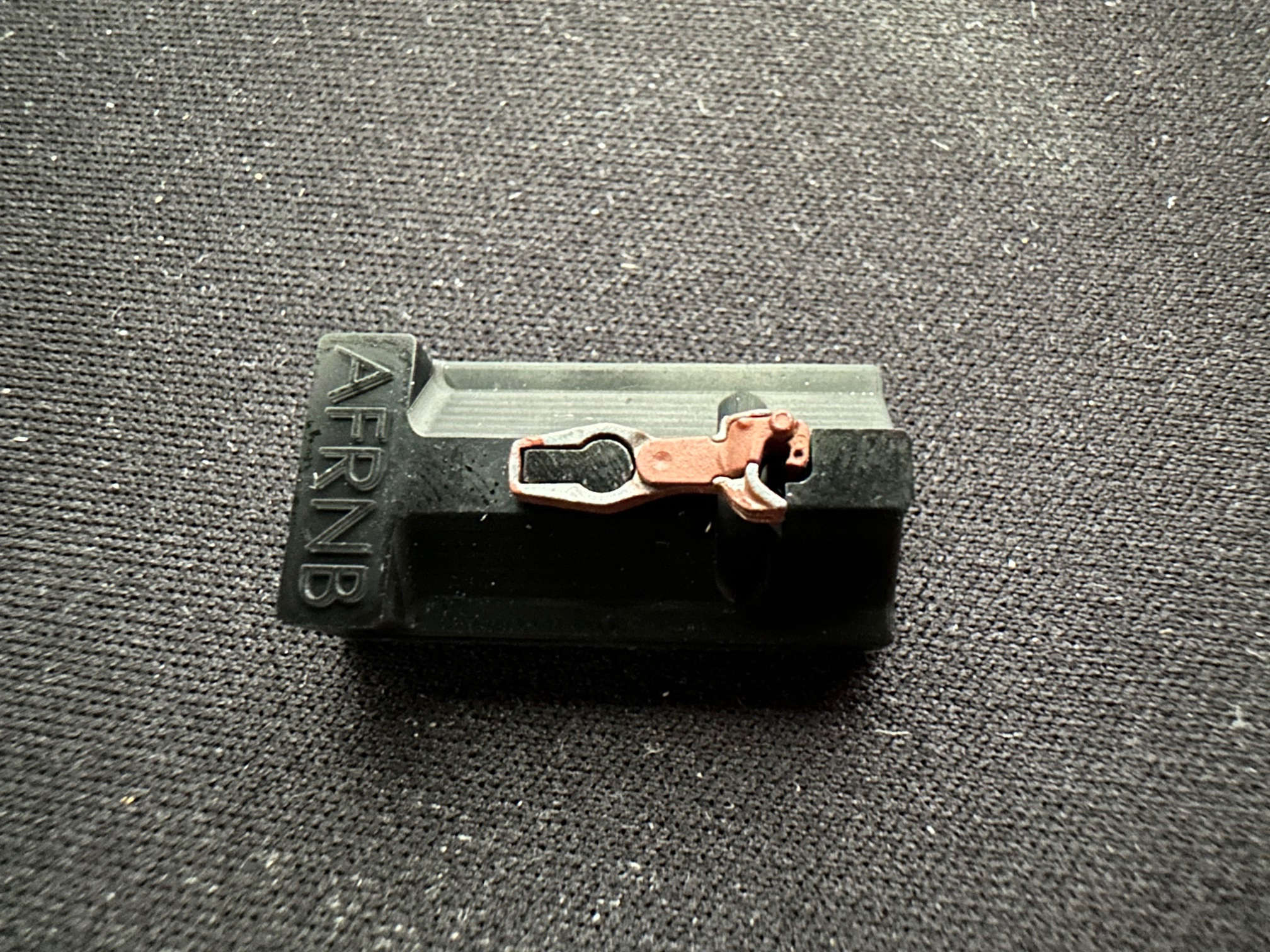
Next comes the bottom cover castings. Fit is snug. Start by aligning the peg on the rear of the bottom cover casting to the hole in the top casting. Then use both hands to seat the cover at front and back simultaneously. You might have to adjust the knuckle position slightly if the bottom cover doesn't want to seat properly in the front. |
 |
|
After installing the bottom cover, another tiny dot of glue should be applied at the head of the couper to the gap between the bottom cover and the top casting as indicated by the red line in the photo. This will prevent the bottom cover from popping off under high stress conditions. |
 |
|
Pull the coupler off to let the glue cure while the coupler is still UPSIDE-DOWN. If the coupler is turned rightside-up before the glue cures fully, there is a chance that the ball will fall into some glue and the coupler will be locked forever. The "forever" part isn't entirely true. Couplers that are assembled with CA can always be taken apart after soaking them in acetone for about five minutes. Leave the coupler in overnight and all traces of the glue will be gone. Do expect to have to repaint the coupler in this case though. |
 |
|
Break-in is essential if the couplers are to operate reliably. Pencil lead (graphite) makes a great lubricant. The first step is to color the mating surfaces thoroughly with a pencil. Be sure the knuckle is covered on both the inside and outside surfaces. |
 |
Once the graphite is applied, the couplers should be operated by hand while upside-down to allow the graphite to find its way into all the inner workings. This will break loose any flash on the mechanism. | |
Next, rake the couplers over each other vertically to polish the surfaces and smooth away any potential operational problems. Turn the couplers right side up and let them lock together. Push them together while you slide them across each other vertically to polish the coupler head socket and front of the knuckles. A little bit of a catch is ok as the knuckle parting lines cross. Now pull them apart while performing the same action. This will polish inner side of the knuckle. |
|
|
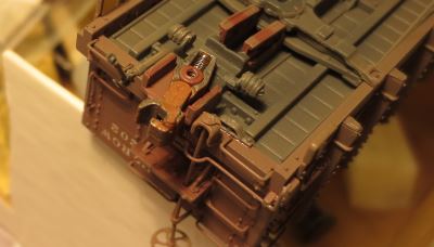
After the break-in procedure it's a good idea to test the couplers by hanging an uncoupling tool off a desk lamp. Couple. Uncouple. Repeat. Go through this a few times until you are confident in the reliability of the couplers. You might notice in the picture that I am holding the one coupler much farther from the magnet than the other. This is on purpose so I unlock only one of the couplers for the test. The Sharon couplers are designed to couple with one knuckle open and the other closed. This is in contrast to the Sergent Engineering AAR couplers that will couple just as reliably with both knuckles open. |
 |
|
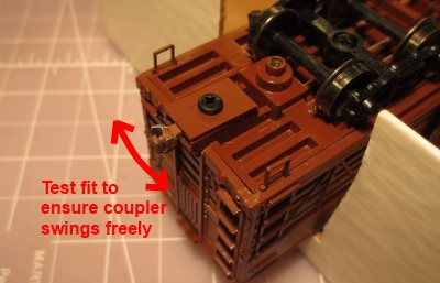
For most installations you'll probably want to use an existing draft gear box that is molded into the underframe of the car. It's best to temporarily install the coupler in these boxes (without the friction spring) to verify that the coupler can move freely side to side (which is very important for the Sharon couplers). Be sure to screw the lid onto the box for this test because many of these problems don't show up until the lid is attached. The Roundhouse stockcar is shown as an example, because Roundhouse cars typically have posts that have swelled and even cracked to make the effective post diameter too big. This is not an uncommon situation for any arragement that uses a screw to hold the lid in place. Blackstone Models HOn3 cars often have swelled post as well. The next two steps show how to deal with the situation when the coupler won't swing freely. If you are using the Accurail narrow boxes that come with the RN87K, you won't have these issues and can skip the next two steps. |
 |
|
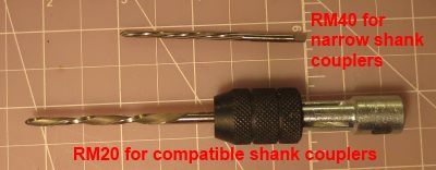
If the car's coupler mounting post is too big for the mounting hole in the coupler, the coupler's mounting hole can be enlarged slightly with a tapered reamer available from Sergent Engineering. The RM20 works for enlarging the big holes in the compatible shank couplers. Since the RM20 reamer is too big to fit in most pin vises, it comes with a its own handle. The RM40 works for enlarging the holes in the narrow shank couplers. It's smaller diameter fits nicely in most pin vises, so no handle is included. Both reamers have spiral cutters that help keep them from biting into the coupler while the hole is being enlarged. The fact that the mounting holes have slots for the springs that interrupt their diameter means there will still be a tendancy for the reamer to bite into the edge of the slot. Work slowly. Test progress by checking fit often as you work. The tapered reamer do the job very quickly and its easy to get carried away. Be very careful with the reamers because they are very SHARP! |
 |
|
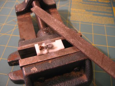
Another potential issue is that the shank of the Sergent Engineering coupler will be too thick for the draft gear box. The Sergent Engineering coupler has a prototypically thick shank. Other couplers typically have a shank that is unprototypically thin so they work fine with these draft gear boxes. My solution for this problem is to use a file to thin the shank of the coupler slightly. Mount a Sergent Engineering assembly fixture in a vise as shown. The vise I use is an old drill press vise from Sears. It's great for all sorts of tasks. Q uality of files vary greatly. I bought this 6" file from Sears as well years ago, and it's outlasted many imports that I tried. Put the coupler on assembly fixture and remove metal from the bottom of the shank with a file. Test fit the coupler and repeat the operation until the coupler swings freely in the box with the lid installed. An alternate method of dealing with this problem is to glue short strips of styrene to the walls of the box so as to shim the lid up a tad. This method works as well, but you have to be careful about tightening the cover screw too much as it will distort the lid and you'll end up with the same binding issue. If you go this route, just barely tighten the lid screw. You might want to dab a little paint on the threads of the screw beforehand so it won't work its way out in the future. |
 |
|
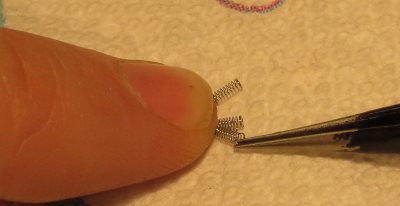
The next step is going to require the friction springs. The light springs included with the Sharon style couplers like each other a lot and so you'll probably have to separate them first. They don't really get tangled together, but they do sort of interleave with each other. The best way to separate a collection of springs is to hold them down on one end with your finger and use tweezers to tease them apart. Don't try to do this with your fingers alone and trying to use tweezers from a drawer in your bathroom won't work much better. See assembly tips for recommendations on tweezers. This is easy with the right tool. |
 |
|
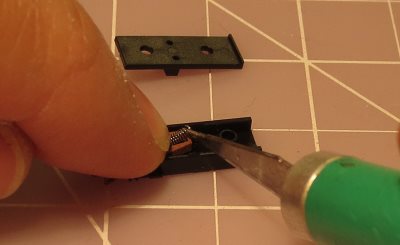
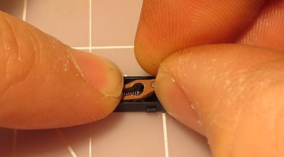
Installing the friction springs is not hard. The trick is to keep your finger over the spring so it can't fly off. The spring can be picked up and located with a hobby knife by pushing the blade into the spring coils. Remove your finger slowly and as you do and make sure the spring is not trying to pop out. If it is, you can use the hobby knife to compress the spring a little and push it farther down into the slot. Only remove your finger when the spring is locked into place. You can insert the coupler first and then add the spring as shown in the top picture. That's the easiest way. Sometimes I prefer the method shown in the bottom picture, especially with the narrow shank couplers. Put the spring into the box first and use the coupler to trap the spring between the post and the slot in the coupler. Then compress the spring as you slip the coupler over its mounting post. This method is a little faster, but sometimes it will drive you nuts if the spring keeps rolling away before you can trap it. Once the spring is in and the coupler is installed, put your finger back over the spring and move the coupler side to side in the box to make sure it moves freely. It's very important that the Sharon couplers can move freely in the box for reliable coupling. Both of these pictures show friction spring installation for an RN87 going in to the supplied Accurail box. Both techniques can be applied for boxes that are cast into the floors of a car as well. |
  |
|
If you have been following along so far and are using a cast-in box to install your coupler into, then you are pretty much done. Just replace the box lid and repeat the exercise for the other end of the car. |
 |
|
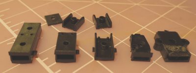
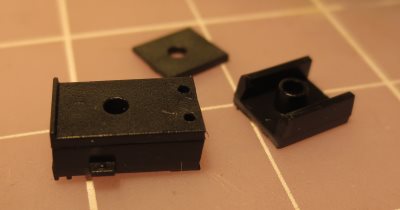
If you plan on using the Accurail box supplied with the the RN87 couplers, you still have some work to do in getting the box mounted to the car. First, let's take a closer look at the boxes. This picture compares several options available to modelers for draft gear boxes for use with Sergent Engineering couplers. The left most box is the stock narrow shank box as supplied with Sergent Engineering narrow shank couplers. The next box is the same thing with the back end chopped off with a hobby knife. Chopping off the back of the box is necessary in instances where the long box would interfere with molded on underframe details (like the body bolster). The middle box is the same chopped-off box with the lid omitted as might be appropriate to raise coupler height. The next box is the one that comes with Kadee 714 HOn3 couplers. Notice that it looks like it's the same size as the Sergent Engineering box minus the lid. That's because it is the same size! The hole is the same size and in the same place well. On the far right is the box that is supplied with Kadee #5 couplers just for completeness that coincidently fits our compatible shank couplers. |
 |
|
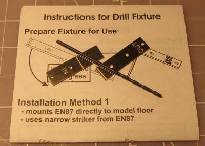
Installing the Accurail box on standard gauge rolling stock probably requires drilling some holes in the floor of the car. Locating these holes is made simple when you use the Sergent Engineering IFN installation toolkit. The kit contains two drill templates, a proper size drill, and instructions detailing how to use these. Many Atlas cars and locos already have these holes, so no drilling is necessary for those installations. |
 |
|
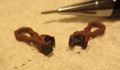
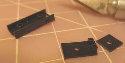
For most HOn3 applications, the Accurail box needs to be shortened. Once this is accomplished, the Accurail box will be basically the same size as a Kadee 714 box and will fit anywhere the 714 box was previously used. Use of the box lid is optional. It can be used or ommitted as needed to obtain correct coupler height. The top picture shows the first step in shortening the box. Use a hobby knife to cut off the rear part of the box lid flush with the attachment boss. Next press the shortened lid into the main part of the box and use the short lid as a guide to chop of the bottom box piece. This is shown in the bottom picture. |
  |