Finishing and Detailing Tips
This section will appear absolutely ludicrous to a modeler that has never seen Sergent couplers in person. The realism of Sergent couplers causes a transformation in the mind of the modeler. The realization that couplers are models too will hit you like a brick. Sergent couplers are addictive. Before long, you'll decide you want even more realism than the straight-out-of-the-pack couplers provide. This section is for that hopeless group of modelers who have reached that point of no return.
Detailing Tip #1 - Fill the cracks
The crack between the top and bottom castings (as well as the stake pin and hole through the shank) is mostly hidden because the draft gear box in most installations. However, it's a pretty easy thing to remove completely as with the type F coupler shown in the picture. First, dab on some Squadron Green Putty (available at your local hobby shop, or just Google it). Use a toothpick to press it into the voids. Then scrape the surface smooth with a hobby knife before the putty completely sets. You'll have to paint the coupler to remove the green-ness, which is discussed below. You can apply the same treatment to fill the small vertical hole that sometimes appears on the face of the knuckle casting as well. A customer pointed out that Bondo glazing & spot putty found in auto parts stores can be used for the same purpose. It's cheaper and it's closer to the right color.
Detailing Tip #2 - Blacken the Cut Lever Linkages
Installing Sergent Engineering etched cut lever linkages (Part Number BCL87) to the bottom type E couplers provides a nice extra detail. However, these linkages are raw brass and so they need to be painted to match the color of the rest of the coupler. As a preparation for the painting operation, the raw brass should be blackened. This serves three purposes. First, it roughs up the surface so the paint will adhere well. Second, it adds a little rough texture to the etched sheet brass so it doesn't look slick. Third, it prevents a shiny spot if the paint does happen to chip off. There are several different companies that sell chemicals to do this and they all seem mostly the same. Here's a link to the version that Micro-Mark sells.
Detailing Tip #3 - Adding Top Operating Loops
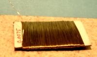
A model freight car with an accurately modeled top operating coupler is impressive. Prototype Couplers offers an option for kit couplers for drilled tops to accept loops needed to represent top operating couplers. Commercial eyebolt castings can be inserted into this hole to make this an easy task. However, these don't look quite right it most cases because they sit too high on the coupler. The loop on the prototype sits low on the horn of the coupler. Loops aren't hard to fabricate from brass wire. In fact this is exactly what Prototype Couplers does for our FT4R87A coupler that is pictured. We use soft brass craft wire that is 0.007" in diameter. This stuff is available from craft stores and even some Wal-Mart stores. Non-model railroaders use it to make jewelry by threading pretty beads onto it. This is better than the 0.010" diameter bronze wire sometimes available at hobby shops because it's softer. It's cheap too and comes in a package with enough wire to last forever.
First prepare some wire. Cut a piece of wire a few inches long. Blacken the wire with a chemical blackening chemical so paint will stick to it when you are done. I blacken lots at a time by winding it into a loose "spring" around a pencil. Let the blackening liquid dry thoroughly.
Many times the drilled hole goes all the way through the top of the coupler into the ball cylinder. The ball cylinder will have to be blocked to keep the inserted wire out. Cut the tip off a round toothpick so it fits tightly into the ball cylinder. Then twist it into the ball cylinder. This will keep the wire from sticking down into the ball cylinder and will keep glue out as well.
Next, cut a short section of the blackened wire maybe an inch long. Drag one end of the wire through a puddle of thick cyanoacrylate (super glue) and insert it into the hole in the top of the coupler. Don't be shy about how much glue to use. The wire won't hold much anyway. Your goal is to completely fill the hole on the top of the coupler. The wire should be sticking more or less straight up. Let this set for a few hours till the glue completely cures.
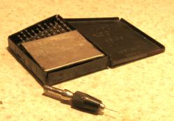
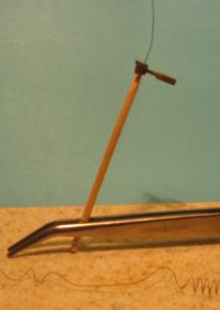
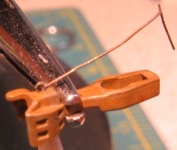
The next step is to form the loop. This is done by wrapping the wire around a small drill and stretching lightly. If you don't have a set of small size drills, you can get them from Micro-Mark. You'll also need something to hold the small drills with. Many pinvises don't do a good job of holding the smallest drills. Again, Micro-Mark has a good selection. Finally, you'll need two straight hemostats to hold the coupler and maneuver/stretch the wire.
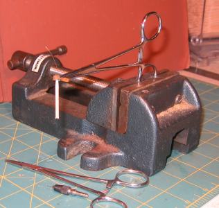
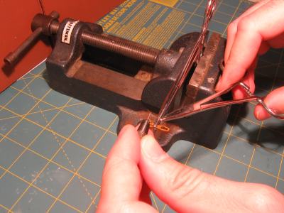
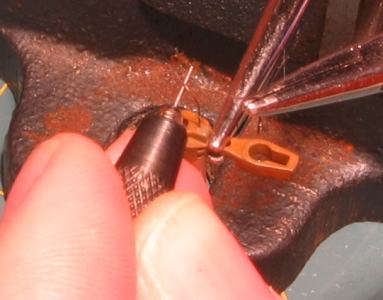
The series of 4 pictures below shows what comes next. The first picture shows the general setup used. Mount a #79 drill in a pinvise. Mount the drill reverse to the normal drilling use. We won't be drilling. We just need the smooth drill shank sticking out. Secure one of the hemostats in a vise. Then secure the coupler in that hemostat. As shown in the next two pictures, gently tease the wire to loosely loop around the drill bit. Pull the wire toward you to tighten the loop. As you do this, move the drill down until it rest on the top of the coupler. Then release the wire and pull the drill out of the loop. It takes a little experience to know how hard you can pull without pulling the wire out of the top of the coupler. If you pull the wire out, just glue it back in and try again. You'll get the hang of it before you know it. The last picture in the group shows the end result after the loop is formed.
We're almost done. Release the coupler from the hemostat and remove the toothpick from the ball cylinder if you haven't already. Place it on a flat surface and insert the tip of a hobby knife through the loop. Cut the soft brass wire against top of the coupler. The cut should be inside the loop - not where the wire exits the loop. Now use the hemostat to adjust the loop slightly to make sure its standing straight up and perpendicular to the face of the coupler. Dab some super glue to both side of the loop for support. Don't worry if the loop gets glue in it because it can easily be removed after the glue cures. Just use the business end of the drill that was used to form the loop in the first place.
After a little paint, the pull loop will look like it's an integral part of the coupler.